Eureka AIR delivers breakthrough ideas for toughest innovation challenges, trusted by R&D personnel around the world.

Coated cutting tool

A cutting tool and cladding technology, which is used in the manufacture of tools, workpieces, drilling tool accessories, etc., can solve the problems of reduced destructive strength and easy occurrence of defects of clad cutting tools.

Active Publication Date: 2016-05-11
TUNGALOY CORP
View PDF7 Cites 7 Cited by
  • Summary
  • Abstract
  • Description
  • Claims
  • Application Information

AI Technical Summary

Problems solved by technology

[0003] Generally, it is generally believed that if a coating film is formed on the surface of tungsten carbide-based cemented carbide, since tensile stress remains in the coating film, the fracture strength of the coated cutting tool is reduced and cracks are likely to occur

Method used


Image

  • Coated cutting tool
  • Coated cutting tool
  • Coated cutting tool

Examples


Embodiment

[0065] Examples are given below to describe the present invention, but the present invention is not limited to these Examples.

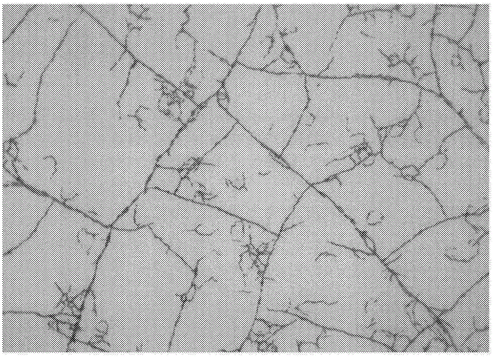
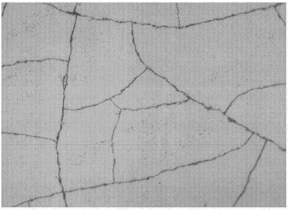
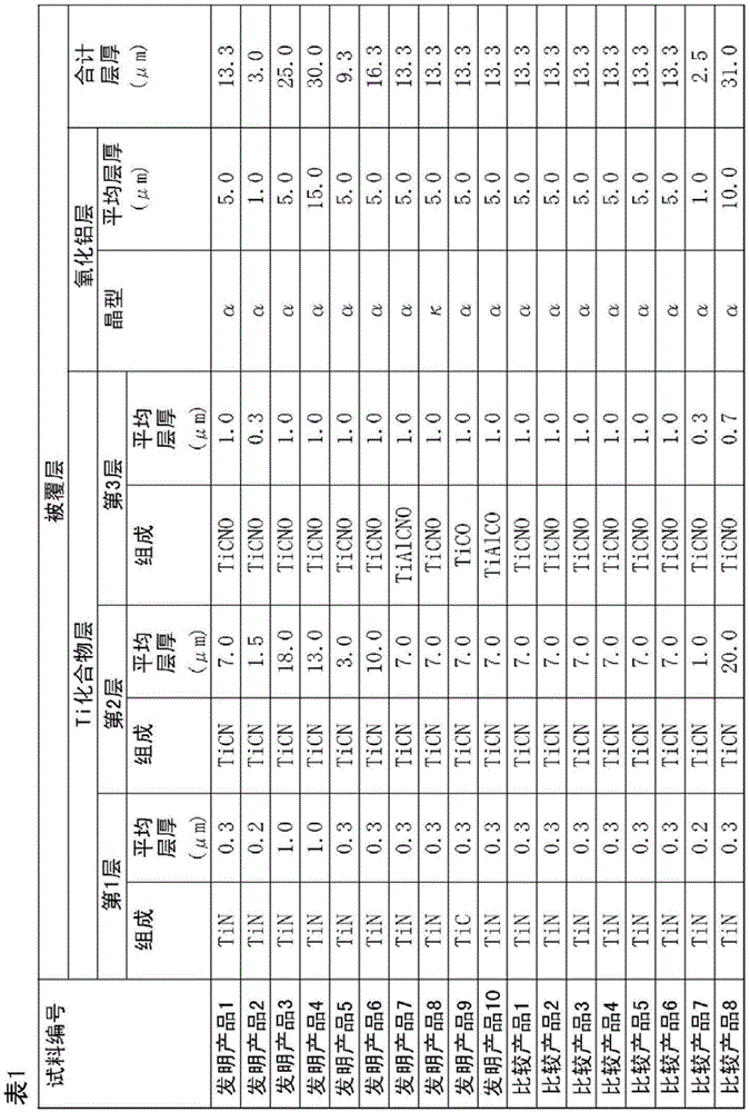
[0066] As a base material, a cutting insert made of cemented carbide having a composition of 86.0WC-1.0TiCN-1.3TaC-0.2NbC-0.5ZrC-11.0Co (the above is mass %) in the shape of JIS standard CNMG120412 was prepared. The surface of the base material was cleaned after circular honing was performed on the cutting edge ridge line portion of the base material with a SiC brush. Next, the base material was placed in an external heating type chemical vapor deposition apparatus, and a coating layer was formed on the surface of the base material so that the composition and average layer thickness of the coating layer shown in Table 1 were obtained. 10 samples were produced for each sample. In addition, the aluminum oxide layer (Al 2 o 3 The α in the crystal form of layer) means α-type Al 2 o 3 layer, κ means κ-type Al 2 o 3 layer.

[0067]The obtained samp...


PUM

PropertyMeasurementUnit
thicknessaaaaaaaaaa
thicknessaaaaaaaaaa
particle sizeaaaaaaaaaa

Abstract

Provided is a coated cutting tool provided with a substrate and a coating layer formed on the outer surface of the substrate in order to obtain a coated cutting tool having superior resistance to chipping, wear and damage while having a long service life, wherein: the coating layer includes at least one Ti compound layer; the Ti compound layer comprising a compound containing elemental titanium and at least one element selected from the group consisting of C, N, O and B; a region surrounded by cracks is provided in the Ti compound layer when a grinding surface substantially parallel to the surface of the substrate is seen from above; the region is internally provided with intermittent cracks in which one end or both ends of the cracks do not abut the cracks that constitute the region; and the average number density (A) of the region and the average number density (B) of the cracks satisfies the relationship of 0.7<B / A<2.

Description

technical field [0001] The present invention relates to a coated cutting tool. Background technique [0002] In the past, it is well known that the coated cutting tool is used for cutting steel and cast iron, etc., wherein the coated cutting tool is formed on the surface of the base material composed of cemented carbide with a total thickness of 3 to 20 μm by chemical vapor deposition. Thick-film vapor deposition forms, for example, a coating layer consisting of a single layer or a multilayer of two or more of Ti carbides, nitrides, carbonitrides, carbonates, carbonitrides, and aluminum oxides. made. [0003] Generally, it is considered that if a coating film is formed on the surface of tungsten carbide-based cemented carbide, since tensile stress remains in the coating film, the fracture strength of the coated cutting tool is lowered and chipping is likely to occur. Hitherto, it has been proposed to release tensile residual stress by generating cracks by shot peening or t...

Claims


Application Information

Patent Timeline
Patent Type & Authority Applications(China)
IPC IPC(8): B23B27/14C23C16/40
CPCC23C16/403C23C16/56C23C16/30B23B51/00B23B27/14B23C5/00C23C14/24B23B27/148B23B2222/16B23B2224/04B23B2224/32B23B2224/36B23B2226/125B23B2226/18B23B2228/105C23C16/34C23C16/36
Inventor 佐藤博之
Owner TUNGALOY CORP
Why Eureka
Eureka Blog
Learn More