Fixed bed hydrogenation reactor and application method thereof

A hydrogenation reactor and the technology of the reactor are applied in the petrochemical field, and can solve the problems of uneven distribution of hydrogen concentration in the catalyst bed, the inability of the reaction material to pass through uniformly, and the reduction of the hydrogenation efficiency of the catalyst, so as to improve the hydrogenation reaction environment, The effect of improving gas-liquid distribution and saving equipment investment

Active Publication Date: 2016-05-18
CHINA PETROLEUM & CHEM CORP +1
View PDF6 Cites 11 Cited by
  • Summary
  • Abstract
  • Description
  • Claims
  • Application Information

AI Technical Summary

Problems solved by technology

Although this central gas extraction can reduce heat exchange energy consumption, this gas-liquid separation method uses the opening of the side wall of the reactor to discharge the gas phase, which may easily cause the reaction materials to not pass through the catalyst bed uniformly.
The hydrogen concentration in the catalyst bed is unevenly distributed, resulting in a large amount of wall flow and bias flow, which reduces the hydrogenation efficiency of the catalyst, and cannot remove alkynes and dienes in the olefin refining reaction.

Method used


Image

  • Fixed bed hydrogenation reactor and application method thereof
  • Fixed bed hydrogenation reactor and application method thereof
  • Fixed bed hydrogenation reactor and application method thereof

Examples


Embodiment 1

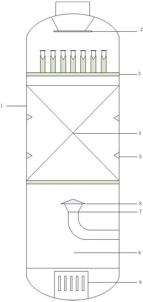
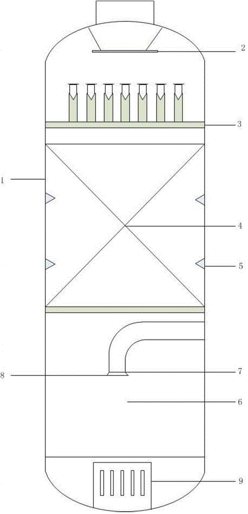
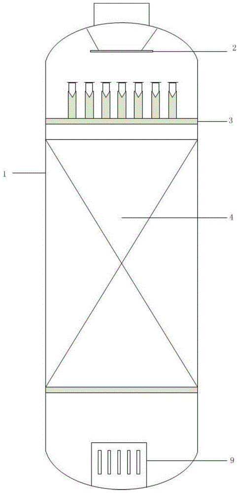
[0028] The fixed bed reactor is sequentially provided with a pre-distributor 2, a gas-liquid distribution plate 3, a catalyst bed 4, a gas-liquid phase separation chamber 6, and a liquid phase separation chamber 6 arranged at the bottom of the cylinder 1 from top to bottom along the axis of the cylinder 1. Phase outlet collector 9;

[0029] The top of the gas-liquid phase separation chamber 6 is provided with a gas phase discharge port 7, and its inner diameter is 16 centimeters. The upward direction of the feed port 7 is provided with a baffle plate 8, which is located directly above the gas phase discharge port 7 and is an upwardly directed cone with a horizontal cross-sectional diameter of 22 cm.

[0030] The height of the catalyst bed is 2.5 meters, and the inner diameter of the reactor cylinder is 1.25 meters. An annular baffle 5 is arranged on the inner wall of the cylinder 1 corresponding to the catalyst bed 4, and there is no gap between the inner wall of the cylinder ...

Embodiment 2

[0033] The top of the gas-liquid phase separation chamber 6 is provided with a gas phase discharge port 7, and its internal diameter is 16 centimeters. The gas phase discharge port 7 is a circular shape with an opening that is the center axis of the gas-liquid phase separation chamber 6 central axes. The downward direction of the discharge port 7 is provided with a baffle 8, which is located at the lower edge of the gas phase discharge port 7 and is in the shape of a flared barrel with a horizontal cross-sectional diameter of 20 cm.

[0034] Other reactor parameters, the reaction conditions of the liquid-phase selective hydrogenation of the C3 fraction to remove methylacetylene and propadiene are the same as in Example 1.

[0035] After the selective hydrogenation reaction, the MAPD content in the liquid phase discharge at the bottom of the reactor is 46ppm, the hydrogen content is 155ppm, and the MAPD and hydrogen content are 1567ppm in the gas phase recovery material.


PUM


Abstract

The invention discloses a fixed bed hydrogenation reactor and an application method thereof. In the fixed bed hydrogenation reactor, a gas-liquid phase product pre-separation technology with gas phase withdrawal in an axial center position is employed, wherein a plurality layers of baffle plates are arranged on the inner wall of the reactor, thereby improving operation stability of the hydrogenation system, improving gas-liquid distribution status in the reactor and eliminating wall flow, deflected flow and the like defects. The reactor, when being used in a reaction process of C3 fraction liquid-phase selective hydrogenation to remove methyl acetylene (MA) and propadiene (PD), can not only increase the MAPD hydrogenation purification reaction efficiency of a propadiene material but also is low in residual hydrogen, so that separation load in a down-stream propylene rectification column is reduced.

Description

technical field [0001] The invention belongs to the field of petrochemical industry, and relates to a hydrogenation reactor, more specifically, to a fixed-bed hydrogenation reactor which adopts gas-liquid phase product pre-separation technology and eliminates wall flow and bias flow, and its application. Background technique [0002] After steam cracking and separation of liquid hydrocarbon raw materials such as naphtha, the C3 fraction contains propylene, propane, and a small amount of propyne and propadiene (abbreviated as MAPD). The content of MAPD is about 1% to 5% (volume) . In propylene polymerization, MAPD will reduce the activity of polypropylene catalyst and affect the quality of polymerization grade propylene products. In order to remove MAPD from the C3 fraction, catalytic selective hydrogenation and solvent absorption are currently used in industry to remove MAPD. Due to the simple process of catalytic hydrogenation and no environmental pollution, the applicati...

Claims


Application Information

Patent Timeline
IPC IPC(8): B01J8/02B01J8/06C10G45/32C07C11/06C07C5/09C07C5/05
CPCY02P20/52
Inventor 卫国宾房艳彭晖乐毅李前戴伟
Owner CHINA PETROLEUM & CHEM CORP
Why Eureka
Try Eureka