Flue gas waste heat recycling boiler with variable space and variable flow fields

A flue gas waste heat recovery boiler technology, applied in fluid heaters, preheating, liquid degassing, etc., can solve the problems of low overall system level, affecting waste heat recovery efficiency, poor performance of heat exchangers, etc., to achieve enhanced heat transfer Thermal effect, good heat transfer effect, effect of ensuring gas flow rate

Active Publication Date: 2016-05-18
GUANGZHOU INST OF ENERGY CONVERSION - CHINESE ACAD OF SCI
View PDF7 Cites 2 Cited by
  • Summary
  • Abstract
  • Description
  • Claims
  • Application Information

AI Technical Summary

Problems solved by technology

[0003] At present, there are many problems in the field of waste heat recovery in my country's iron and steel metallurgy industry. First, a large part of small and medium-sized enterprises have backward equipment, and the sensible heat of waste heat carriers such as flue gas cannot be effectively preserved. The short circuit of the pipeline and the poor heat insulation of the pipeline make the heat loss of the flue gas of many furnaces before the recovery device very large
Secondly, the comprehensive utilization of waste heat is relatively poor, and most of the waste heat is only used once
In addition, because most of the high-temperature waste heat has not been fully utilized at present, the utilization of medium and low-temperature waste heat has not received enough attention, and it is impossible to really make the best use of it.
Furthermore, waste heat recovery equipment and systems are not perfect
Some waste heat utilization equipment such as heat exchangers have poor performance, which affects the overall waste heat recovery efficiency
Some waste heat recovery equipment has excellent performance, but because the design of the overall system is not scientific and reasonable, the overall level of the system is not high. The system is inefficient and even affects its service life

Method used


Image

  • Flue gas waste heat recycling boiler with variable space and variable flow fields
  • Flue gas waste heat recycling boiler with variable space and variable flow fields
  • Flue gas waste heat recycling boiler with variable space and variable flow fields

Examples


Embodiment Construction

[0017] The present invention will be further described below in combination with specific embodiments.

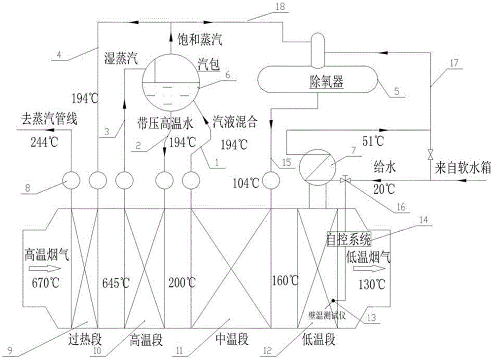
[0018] like figure 1 As shown, the flue gas waste heat boiler with variable space and variable flow field of the present invention includes an economizer outlet pipe 1, an evaporator descending pipe 2, an evaporator ascending pipe 3, a superheater inlet pipe 4, a deaerator 5, and a drum 6. Low temperature section steam drum 7, header pipe 8, superheater 9, evaporator 10, economizer 11, YHSP heat exchanger 12, wall temperature detection point 13, automatic control system 14, deaerator outlet pipe 15, automatic Control valve 16, water inlet pipe 17 of deaerator, steam inlet pipe 18 of deaerator.

[0019] The heat carrier of this boiler is industrial flue gas, in which water / steam go through the tube side, and flue gas goes through the shell side. The boiler includes a horizontal furnace body, the furnace body from left to right is a high temperature flue gas inlet, a superh...


PUM


Abstract

The invention discloses a flue gas waste heat recycling boiler with a variable space and variable flow fields. The flue gas waste heat recycling boiler adopts four heat absorption sections, wherein a low-temperature heat absorption section adopts a low-temperature near-dew-point anti-corrosion flue gas high-efficiency recycling and energy-saving heat exchange YHSP device, so that the inlet water temperature of a medium-temperature heat absorption section is increased by the low-temperature heat absorption section, and the device does not generate acid dew corrosion under the working condition that boiler load continuously changes. Besides, the heat exchange equipment of the boiler adopts SP high-efficiency heat exchange tubes, so that the good strengthened heat transfer effect is achieved, pressure drop is reduced when gas flow velocity is guaranteed, vibration does not likely occur, and scale inhibition and tube explosion prevention are relatively high. Compared with a conventional waste heat recycling device, the volume of the boiler is reduced by 20-30%, and the weight of the boiler is reduced by 30-40%, so that the low-temperature waste heat recycling, energy conservation and emission reduction of the flue gas are realized.

Description

technical field [0001] The invention relates to the field of waste heat recovery and utilization, in particular to a flue gas waste heat recovery boiler with variable space and variable flow field. Background technique [0002] my country's energy utilization has always been extensive growth, low energy utilization efficiency, and poor economic benefits have always been the main problems in my country's energy utilization. In our country, industrial waste heat, such as industrial enterprises, is very rich in unused energy resources in thermal energy conversion equipment and energy-consuming equipment in the production process, totaling more than 40 million tons of standard coal. Especially in the iron and steel industry, the amount of residual heat resources accounts for 10.4% of the total amount of waste heat resources in my country. However, the recovery rate of remaining heat resources is only 21.7%. Therefore, improving the utilization rate of waste heat resources in t...

Claims


Application Information

Patent Timeline
Patent Type & Authority Applications(China)
IPC IPC(8): F22B1/18F22D1/02F22D1/50F24H1/00
CPCF22B1/18F22D1/02F22D1/50F24H1/00
Inventor 朱冬生张洁娜涂爱民莫逊
Owner GUANGZHOU INST OF ENERGY CONVERSION - CHINESE ACAD OF SCI
Why Eureka
Try Eureka