Argillaceous biomass refuse solar interlayer drying device and two-stage drying method

A technology of biomass and solar energy, applied in chemical instruments and methods, waste treatment, transportation and packaging, etc., can solve the problems of large floor area and low efficiency of solar energy utilization, save site area, reduce device volume, improve dryness The effect of melting rate

Active Publication Date: 2016-06-01
SHANGHAI JIAO TONG UNIV
View PDF2 Cites 2 Cited by
  • Summary
  • Abstract
  • Description
  • Claims
  • Application Information

AI Technical Summary

Problems solved by technology

[0006] The purpose of the present invention is to overcome the shortcomings of the existing solar sludge drying system, such as large footprint and low solar energy utilization efficiency, and adopt a method of combining solar direct heating drying and solar heat pump supply indirect drying, and utilize solar waste heat system, Build a solar interlayer drying device. The upper layer is directly heated and dried by solar panels, and then the sludge is dropped from the upper layer to the lower layer to turn over the stack. The lower layer uses the temperature of the residual heat of the air source in the interlayer and the steam heating system of the reclaimed water source generated by the solar energy. Thereby improving the efficiency of sludge drying, reducing the area occupied by facilities, and greatly improving social and economic benefits

Method used


Image

  • Argillaceous biomass refuse solar interlayer drying device and two-stage drying method
  • Argillaceous biomass refuse solar interlayer drying device and two-stage drying method
  • Argillaceous biomass refuse solar interlayer drying device and two-stage drying method

Examples


Embodiment 1

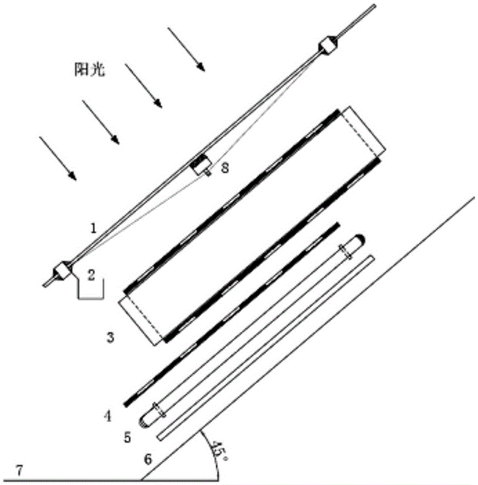
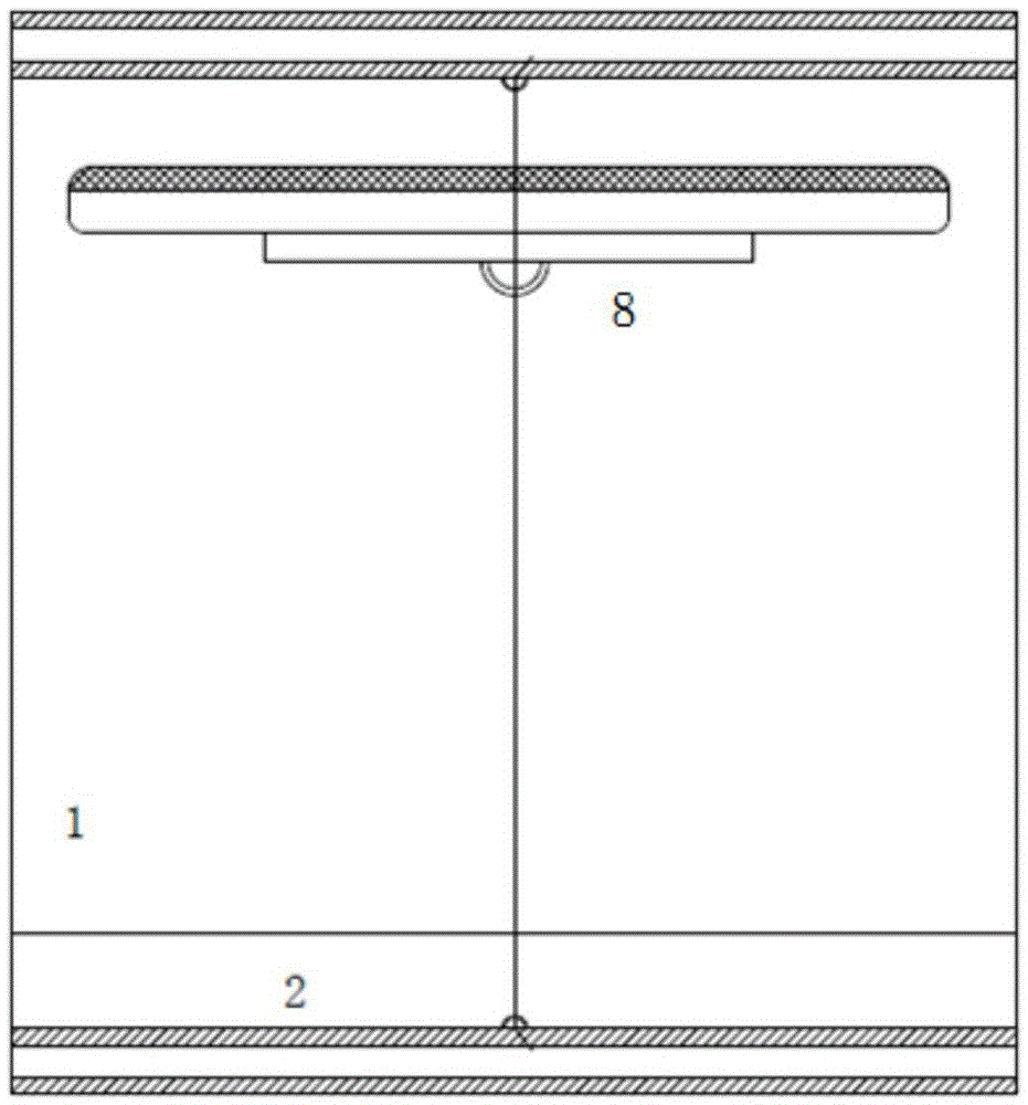
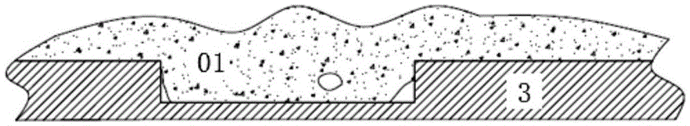
[0060] After dehydration, the moisture content of the sludge is 90%. Through the high-pressure pump or other mechanical distributing system, the sludge is evenly laid on the upper conveyor plate with a thickness of 0.5cm, and then enters the flexible conveyor belt 3. The temperature is 72-82°C during the day and at night. 15-40°C, after drying for 1.5 days, its moisture content will reach 40%; then transfer to the right end of the flexible conveyor belt 3, use gravity and scraper system to scrape off the sludge, enter the rigid conveyor belt 4, use the airtight interlayer The air source in the space and the reclaimed water source heat pump heating system 5 on the back are further dried, and the final moisture content reaches <20%; the dried sludge enters the collecting tank and the lower part by using the mechanical scraper and gravity. One-step utilization mode; the water vapor evaporated during the process is condensed on the light-transmitting layer 1, and the condensed wate...


PUM

PropertyMeasurementUnit
widthaaaaaaaaaa

Abstract

The invention relates to an argillaceous biomass refuse solar interlayer drying device and a two-stage drying method. The drying device comprises an euphotic layer, a flexible conveyer belt, a rigid conveyer belt, a reclaimed water source heat pump heating system and a thermal-insulation layer which are sequentially arranged from top to bottom, wherein a thermal-insulation material is arranged around the four sides to reduce the heat dissipation; and the thermal-insulation material euphotic layer and the thermal-insulation layer form a thermal-insulation interlayer space. The drying method comprises the following steps: argillaceous biomass refuse is laid on the upper flexible conveyer belt, and heated by solar direct radiation to implement predrying formation, deodorization, sterilization and photocatalytic denaturation until the water content is less than 40%; the dried biomass refuse falls onto the lower rigid conveyer belt from the flexible conveyer belt while automatic pile turning is implemented, and is heated again by independently using the air source in the interlayer space or jointly using the reclaimed water source heat pump heating system below until the water content is less than 20%, thereby finally implementing the two-stage drying. The solar direct drying-indirect drying combined mode is utilized to implement drying and dewatering on the argillaceous biomass refuse; and the device and method have the advantages of high drying efficiency and favorable environmental protection effect.

Description

technical field [0001] The invention relates to a treatment method for solid waste, in particular to a solar interlayer drying device and a two-stage drying method for drying argillaceous biomass waste, and belongs to the technical field of environmental protection. Background technique [0002] Muddy biomass waste includes sludge, kitchen waste, blue-green algae, feces and other organic wastes with high moisture content, small particle size, and easy to form mud. The present invention treats sludge as a typical muddy waste. [0003] With the continuous improvement of my country's urban sewage treatment rate, the sludge output of urban sewage treatment plants has also increased sharply. As of the end of June 2013, 3,479 urban sewage treatment plants have been built nationwide, with a sewage treatment capacity of about 120 million cubic meters per day. The most direct result of the large-scale construction and operation of sewage treatment plants is a substantial increase in...

Claims


Application Information

Patent Timeline
Patent Type & Authority Applications(China)
IPC IPC(8): C02F11/12B09B3/00
CPCC02F11/12C02F2303/04C02F2303/02B09B3/00B09B2101/02B09B3/40Y02W10/37Y02W30/20
Inventor 楼紫阳钱盘生朱南文周品尹常凯胡静袁海平
Owner SHANGHAI JIAO TONG UNIV
Why Eureka
Try Eureka