Solar energy-driven coal pyrolysis coupling coalite gasification reactor and method

A gasification reactor, solar energy technology, applied in the gasification process, granular/powder fuel gasification, energy input, etc., can solve the problems of difficulty in ensuring energy utilization efficiency, increasing the cost of oxygen, and low calorific value, etc. Improve the efficiency of energy utilization and conversion, increase the calorific value, and simplify the effect of the control process

Inactive Publication Date: 2016-06-01
NORTHWEST UNIV(CN) +1
View PDF7 Cites 11 Cited by
  • Summary
  • Abstract
  • Description
  • Claims
  • Application Information

AI Technical Summary

Problems solved by technology

[0003] 1) The loss of energy, material and heating gas during the transfer and exchange of mass, momentum, energy and reaction products between reactors is unavoidable;
[0004] 2) To maintain the quality and heat balance of the system, the pyrolysis reactor must provide enough semi-coke particles for the gasifier to release enough heat by incomplete combustion with oxygen. The content of semi-coke depends on the amount of pyrolysis products, while The content of oxygen affects the content of carbon dioxide in the syngas and the yield of semi-coke during the pyrolysis process. The system needs to be finely controlled, and continuous production must be established within a strict operating range. The complexity of the operation makes it difficult to ensure the maximum energy utilization efficiency and target products ;
[0005] 3) Essentially, the heat source of this process is the incomplete oxidation of coal, so although the syngas it produces is clean, its calorific value is not too high, and the use of oxygen increases the cost of system operation

Method used


Image

  • Solar energy-driven coal pyrolysis coupling coalite gasification reactor and method
  • Solar energy-driven coal pyrolysis coupling coalite gasification reactor and method

Examples


Embodiment Construction

[0027] The present invention will be described in detail below in conjunction with the accompanying drawings.

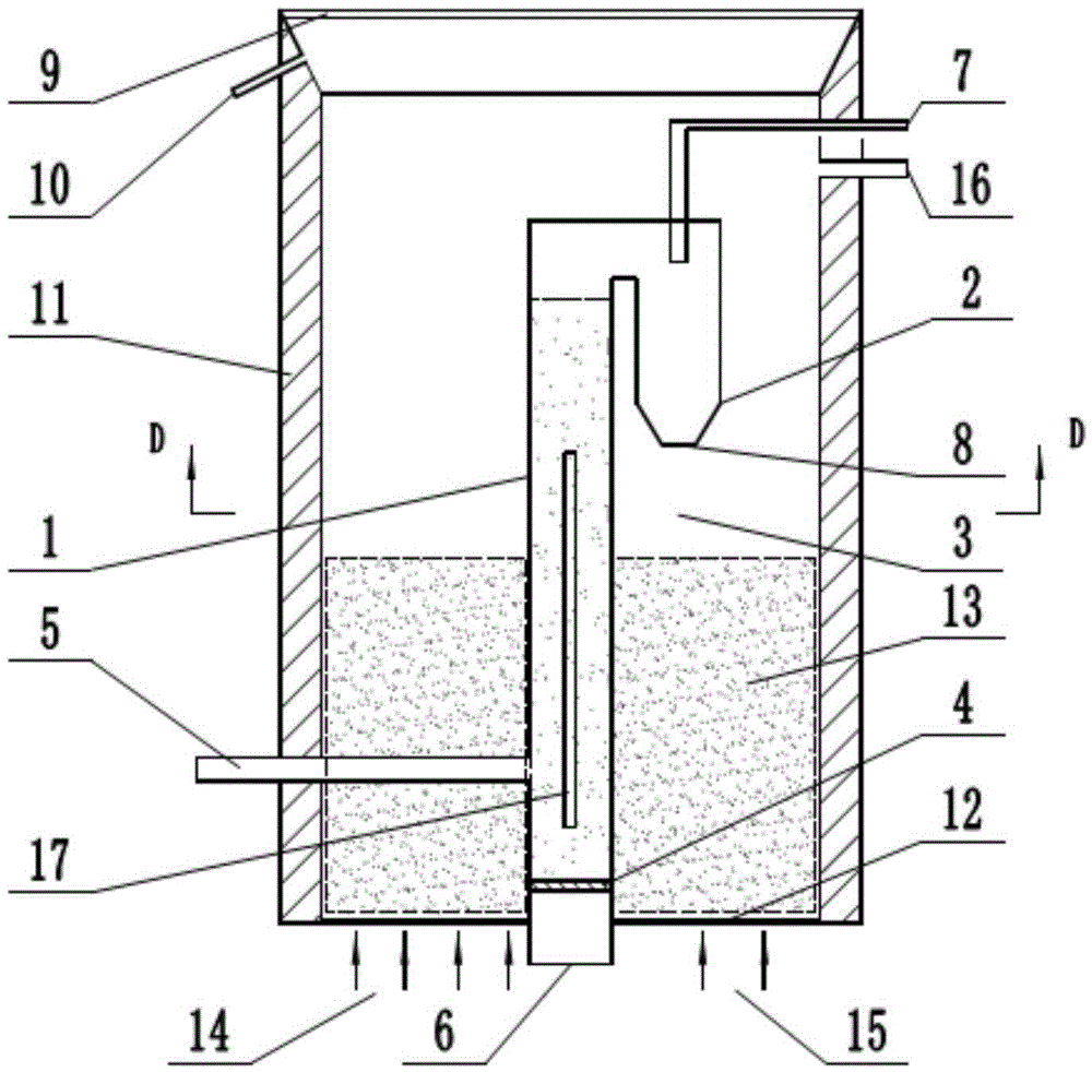
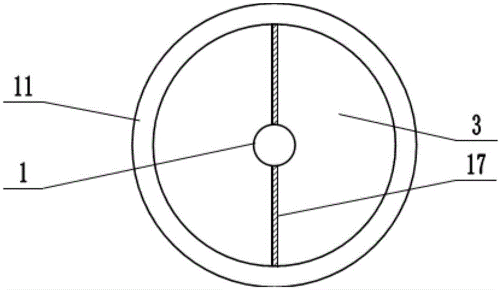
[0028] Such as figure 1 As shown, the present invention includes: a riser 1, a cyclone separator 2, an annular circulating fluidized bed 3, a riser air distribution plate 4, a coal supply pipe 5, a light-transmitting window 9, an insulating layer 11 and an annular air distribution plate 12. Wherein, a riser 1 is vertically arranged in the circulating fluidized bed 3 in the annular space, see figure 2 , the riser 1 is arranged at the center of the circulating fluidized bed 3 in the annulus, and the outer wall of the riser 1 is connected with the inner wall of the circulating fluidized bed 3 in the annulus through a baffle 17 . The upper end of the riser 1 is provided with a cyclone separator 2, and the riser 1 communicates with the cyclone separator 2, the cyclone separator 2 is arranged inside the circulating fluidized bed 3 in the annular space, and the top of th...


PUM


Abstract

The invention discloses a solar energy-driven coal pyrolysis coupling coalite gasification reactor and a method. The reactor mainly comprises a lifting pipe, a cyclone separator and an annulus inner circulation fluidized bed, wherein an outlet of the lifting pipe is connected to the cyclone separator, and the lifting pipe and the cyclone separator are arranged inside the annulus inner circulation fluidized bed; the lifting pipe is located at the center of the annulus inner circulation fluidized bed, a pipe wall of the lifting pipe is parallel to the wall surface of the annulus inner circulation fluidized bed, and an inlet of the lifting pipe extends out of the bottom of the annulus inner circulation fluidized bed for a distance; an air distributor is arranged at the bottom of the lifting pipe, and a coal feeding pipe is connected to the side wall of the lifting pipe; the top of the annulus inner circulation fluidized bed is provided with a light inlet window, the outer wall of the annulus inner circulation fluidized bed is coated with a heat insulation layer, and the bottom of the annulus inner circulation fluidized bed is provided with an annular air distributor.

Description

technical field [0001] The invention relates to the technical field of high-efficiency utilization of solar energy and clean coal conversion, in particular to a reactor and method for coal pyrolysis coupled with semi-coke gasification driven by solar energy. Background technique [0002] Coal is an important energy and chemical raw material in our country, and the utilization of coal in different grades is an important way to realize the efficient and clean utilization of coal. Low-metamorphic coal accounts for more than 40% of my country's coal reserves. It has the characteristics of high volatile content, low ash, low sulfur, low phosphorus and high calorific value, and is an ideal chemical raw material. The technology of low-temperature pyrolysis coupled with high-temperature semi-coke gasification of low-metamorphic coal can improve the energy utilization efficiency of low-metamorphic coal and produce high value-added chemical products (benzene-toluene-xylene BTX) and sy...

Claims


Application Information

Patent Timeline
Patent Type & Authority Applications(China)
IPC IPC(8): C10J3/66C10J3/54C10J3/56C10J3/84C10J3/72
CPCC10J3/54C10J3/56C10J3/66C10J3/72C10J3/84C10J2300/0936C10J2300/1292Y02P20/133
Inventor 魏利平李振华
Owner NORTHWEST UNIV(CN)
Why Eureka
Try Eureka