
Serial thermal printing light emitting display

A display and thermal transfer technology, applied in the direction of electric solid devices, circuits, electrical components, etc., can solve the difficulty of illuminant lattice, the lack of thermal transfer temperature gradient viscosity gradient in the transfer layer, and the high particle size of inorganic electroluminescent powder. Diameter and other problems to achieve reliable transfer effect

Inactive Publication Date: 2016-06-08
汤宝林
View PDF14 Cites 5 Cited by
  • Summary
  • Abstract
  • Description
  • Claims
  • Application Information

AI Technical Summary

Problems solved by technology

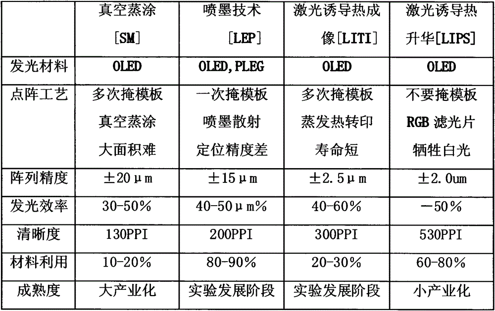
[0031] 3. The laser-induced thermal imaging ribbon and the printing surface are not transferred immediately after point-to-point thermal transfer, but are uncovered after full-scale photothermal scanning. The transfer layer lacks the temperature gradient necessary for thermal transfer. Viscous gradient, not conducive to the reliable and complete transfer of the transfer layer to the printing surface
However, the generation technology of its electroluminescent body lattice is the most complicated etching process: after the inorganic electroluminescent powder "converting material" is mixed with UV photoresist, it is coated on the blue fluorescent layer, and then irradiated by UV light, Forming, and then removing excess material, the subsequent layer is also produced in the same steps..." Inorganic electroluminescent powder has a high particle size and high specific gravity, and the generation of luminous body lattices is difficult to choose from other printing methods, inkjet technology, laser Heat-induced thermal transfer is even more impossible

Method used


Image

  • Serial thermal printing light emitting display
  • Serial thermal printing light emitting display
  • Serial thermal printing light emitting display

Examples


Embodiment Construction

[0075] 1.0 Example target: Serial thermal transfer flexible full-color display (screen) (STP-FOLED)

[0076] 2.0 Product structure: PET(Panel) / Anode<PSTFT / HTL / RGBEML&IFL / ETL / Cathode / PET(Blind)

[0077] 3.0 drive mode: active matrix OLED drive display system [301] (TCL, LG, etc.)

[0078] 4.0 Display panel: BOPET, thickness 75-100μm / Anode<PSTFT [401] (Outsourcing, such as Taiwan Qijing Optoelectronics. Choose the largest area, the highest number of lines. When the resolution of the image number circuit is not enough, choose multilayer LTPSTFT, multilayer ITO Technology. The production of displays with ITO glass plates is similar to this embodiment).

[0079] 5.0 Production of display cover / cathode / electron transport layer:

[0080] 5.1BOPET, thickness 50-75μm, width 900-1000mm; vacuum evaporation Mg / Ag, thickness 0.15μm; then vacuum evaporation Ag, thickness 0.05μm, [501].

[0081] 5.2 Manufacturing of electron transport layer coatings: 3.0-5.0% Butyl-PBD, 2.0-3.0% acrylates, 2.0-3.0...


PUM


Abstract

A serial thermal printing light emitting display is of a different-combination laminated structure composed of a panel, electrodes, an electroluminescent layer and auxiliary function layers. The lattice of the electroluminescent layer or other auxiliary function layers is generated through serial digital thermal transfer printing of an LED serial printing thermal transfer ribbon [LED SP-TTR] (narrow) containing at least one material of the layer directly or indirectly, once or multiple times and in a collocation or multilayer overlay mode, and the lattice can be cross-linked after transfer printing. The display area and display resolution are only limited by the ITO capability, a roll-to-roll (R2R) continuous production process can be adopted more often, and the production process is applicable to the production of super-QXGA or WUXGA full-color displays. The transfer lattice can be generated without a 'mask plate' or 'slot hole'. The process is simplified, and the cost is reduced. The maximum pixel of the display is 2400PPI. Manufacture of a large-size display is no longer limited by the size of an evaporating dish (VTE) or a reaction chamber (OVPD).

Description

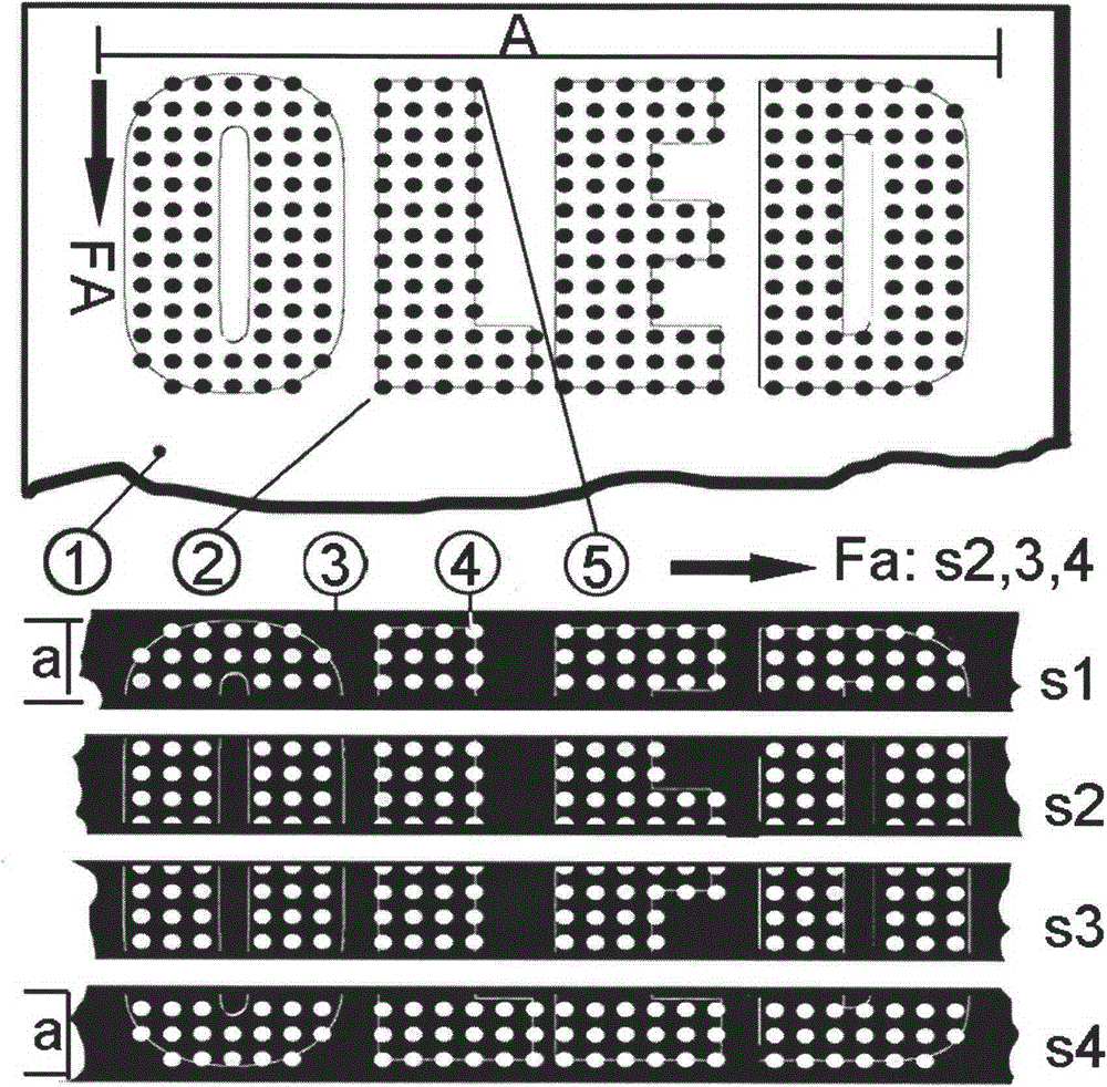
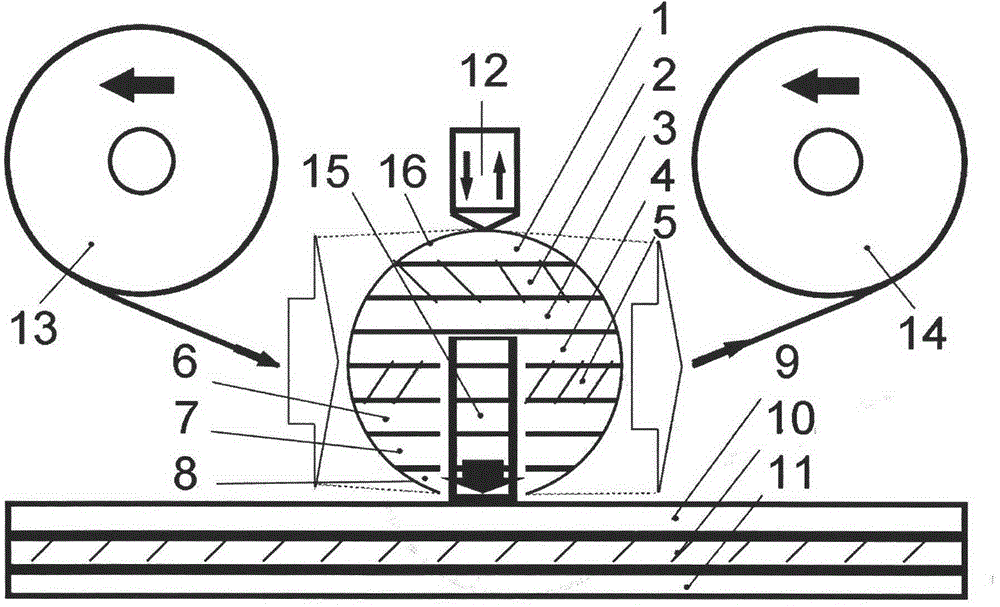
Technical field [0001] A display (screen), a digital printing type electroluminescence display. The present application is a serial thermal transfer electroluminescence display. [0002] Serial thermal transfer electroluminescent display [STP-LED: SerialThermalPrintingLightEmittingDisplay] has a laminated structure of different combinations of panels, electrodes, electroluminescent layers [EML] and its auxiliary functional layers. The transfer dot matrix of the light-emitting layer or other auxiliary functional layer is made of LED serial thermal transfer ribbon containing at least one of these layer materials [LEDSP-TTR: LEDSerialPrintingTTR] directly or indirectly, one or more times, juxtaposed [Collocation ] Or superimposed [MultilayerOverlay], serial thermal transfer generation, and cross-linking after transfer [Cross-linkingafterTransfer] option. [0003] The above-mentioned [0002] serial thermal transfer electroluminescence display, including: liquid crystal display [LCD] [AM...

Claims


Application Information

Patent Timeline
Patent Type & Authority Applications(China)
IPC IPC(8): H01L27/32H01L51/00H10K99/00
Inventor 汤宝林
Owner 汤宝林
Learn More