Glass ceramic body static inhibitor and preparation method thereof

A technology of glass ceramics and electrostatic suppression, which is applied in the direction of circuits, electrical components, overvoltage arresters with spark gaps, etc. It can solve the problems of large electrical range span, low energy, and high initial trigger voltage of products, and achieve consistent product performance and precision The effect of the control

Active Publication Date: 2016-06-08
SHENZHEN SUNLORD ELECTRONICS
View PDF5 Cites 1 Cited by
  • Summary
  • Abstract
  • Description
  • Claims
  • Application Information

AI Technical Summary

Problems solved by technology

[0002] With the development of communication technology, the transmission rate of communication equipment is increasing day by day. In order to prevent the attenuation and distortion of the signal during high-speed signal transmission caused by capacitance, a large number of polymer electrostatic suppressors, polymer electrostatic suppressors and other products have emerged in large numbers. The ESD (Electro-Static discharge, electrostatic discharge) protection on the high-speed transmission signal line has a certain effect, but this series of products are prone to failure during long-term use. Most of the failure modes are short circuits caused by the failure of internal functional materials, and due to Functional materials always contain a certain amount of organic matter, which leads to a high initial trigger voltage of the product and a large span of electrical properties
However, in the IC module, the electrostatic peak is small and the energy is low, so that this kind of product cannot be triggered when it is used in the IC module, and it is impossible to control the clamping voltage within the allowable error range of the IC module.

Method used


Image

  • Glass ceramic body static inhibitor and preparation method thereof
  • Glass ceramic body static inhibitor and preparation method thereof
  • Glass ceramic body static inhibitor and preparation method thereof

Examples


Embodiment 1

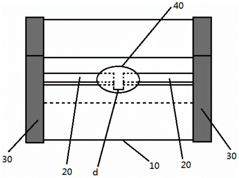
[0033] This embodiment specifically provides a figure 1 The glass-ceramic body static suppressor shown, figure 1 It is a three-dimensional view, and at the same time, the inside of the glass-ceramic substrate is displayed in perspective. Such as figure 1 As shown, the side inner electrodes in this embodiment are arranged opposite to each other in the conductive direction, and the inner ends of the two electrodes are separated by the predetermined distance to form the capacitor structure. When static electricity is generated, the voltage of static electricity is applied to both ends of the capacitive structure, assuming that the breakdown voltage required to break down the gas between two conductors with a distance of d (that is, the inner electrodes on both sides) is V1, then as long as When the peak voltage of the generated static electricity reaches V1, the gas in the capacitor structure in the cavity structure 40 can be broken down to be in a conduction state, and the ele...

Embodiment 2

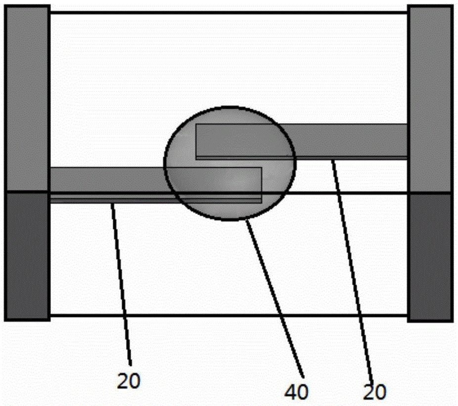
[0035] This specific embodiment provides a kind of figure 2 The glass-ceramic electrostatic suppressor shown differs from Embodiment 1 in that the structure of the side inner electrodes is different. Specific as figure 2 As shown, the two side internal electrodes 20 are arranged in dislocation in the conductive direction, and on the horizontal plane, the two side internal electrodes have overlapping parts in the direction perpendicular to the conductive direction, and the overlapping parts are spaced apart by the predetermined pitch to form the capacitive structure.

Embodiment 3

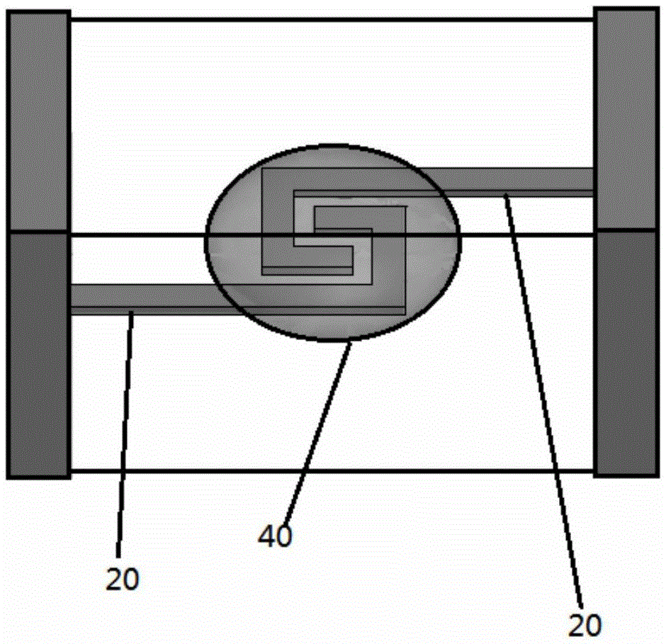
[0037] This specific embodiment provides a kind of image 3 The glass-ceramic electrostatic suppressor shown is different from Embodiment 1 in that: the two side inner electrodes 20 are arranged in a misaligned direction in the conductive direction, and the inner ends of the two form a folded structure with opposite folding directions. The two folded structures with opposite folding directions are misplaced and spiraled on the horizontal plane, so that there is an overlapping portion between the two inner electrodes on the horizontal plane, and the overlapping portions are separated by the predetermined distance to form the The structure of the capacitor.

[0038] Another specific embodiment of the present invention also provides a method for preparing a glass-ceramic static suppressor, which can be used to prepare the glass-ceramic static suppressor provided in the foregoing specific embodiment, specifically comprising the following seven steps:

[0039] S1. Ball milling the...


PUM

PropertyMeasurementUnit
thicknessaaaaaaaaaa
thicknessaaaaaaaaaa

Abstract

The invention provides a glass ceramic body static inhibitor and a preparation method thereof. The static inhibitor comprises a glass ceramic substrate, a pair of inner-side electrodes and a pair of outer-side electrodes, wherein the inner-side electrodes and the outer-side electrodes are respectively positioned on the inner and outer sides of the glass ceramic substrate. The static inhibitor further comprises a cavity structure arranged inside the glass ceramic substrate. Through filling an organic filler, the sintering temperature and the sintering atmosphere during the manufacturing process of the glass ceramic substrate can be controlled, so that the glass ceramic substrate is formed through the splitting decomposition of the organic filler. Meanwhile, the interior of the glass ceramic substrate contains at least one part of gases generated during the splitting decomposition process of the organic filler. The pair of inner-side electrodes is positioned in the same horizontal plane. The outer end portions of the inner-side electrodes are respectively connected with the pair of outer-side electrodes at the two ends of the glass ceramic substrate. Meanwhile, the two inner-side electrodes are arranged at a preset interval to form a capacitor structure. At least the capacitor structure is enclosed inside the cavity structure. The preparation method is used for preparing the above static inhibitor. The static inhibitor is long in life cycle and is not easily invalid even after being used for a long period of time. Meanwhile, the short-circuit risk does not easily occur, and the triggering voltage is relatively low.

Description

technical field [0001] The invention relates to a glass ceramic static suppressor and a preparation method thereof. Background technique [0002] With the development of communication technology, the transmission rate of communication equipment is increasing day by day. In order to prevent the attenuation and distortion of the signal during high-speed signal transmission caused by capacitance, a large number of polymer electrostatic suppressors, polymer electrostatic suppressors and other products have emerged in large numbers. The ESD (Electro-Static discharge, electrostatic discharge) protection on the high-speed transmission signal line has a certain effect, but this series of products are prone to failure during long-term use. Most of the failure modes are short circuits caused by the failure of internal functional materials, and due to Functional materials always contain a certain amount of organic matter, which leads to a high initial trigger voltage and a wide electri...

Claims


Application Information

Patent Timeline
Patent Type & Authority Applications(China)
IPC IPC(8): H01T4/12H01T1/22H01T21/00
CPCH01T1/22H01T4/12H01T21/00
Inventor 杜士雄冯志刚贾广平
Owner SHENZHEN SUNLORD ELECTRONICS
Why Eureka
Try Eureka