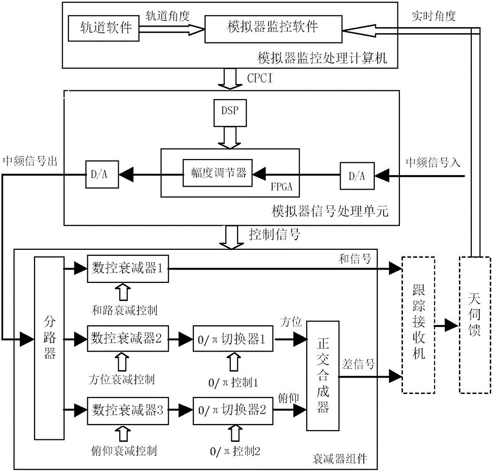
In the angle tracking system simulator, the controllable attenuation range of the attenuator used to control the signals of the azimuth
branch and the
pitch branch is not wide enough, less than 40dB, and the accuracy is not high, greater than 0.1dB, or calculated according to the tracking antenna pattern in the monitoring and
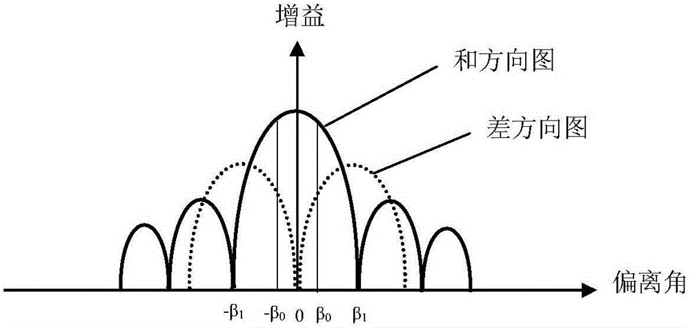
processing computer The correspondence between the offset angle of the antenna and the target and the relationship between the signal amplitude of the road, azimuth
branch, and
pitch branch. The angle offset range of the pre-designed
lookup table does not completely cover the beam width of the
main lobe of the antenna, and the attenuation range that can be checked is not wide enough. Less than 40dB, the accuracy is not high, greater than 0.1dB, or the orthogonality of the quadrature synthesizer used to synthesize the azimuth branch signal and the elevation branch signal into the differential signal is lower than 90°±1°, or the attenuator is controlled Adjusting the amplitude of the azimuth branch signal and the pitch branch signal causes the
phase change to be greater than ±1°, resulting in the orthogonality of the synthesized signal being lower than 90°±3°, which will cause the angle tracking system simulator to control the azimuth during the
simulation angle tracking process. The pitch branch is affected when the branch amplitude is controlled, and the azimuth branch is affected when the pitch branch amplitude is controlled, resulting in cross-coupling; the angle tracking system simulator monitoring
software accesses the
lookup table according to the difference between the real-time antenna angle and the simulated
orbit angle, And the look-up table of the offset angle between the antenna and the target calculated according to the tracking antenna pattern and the relationship between the signal amplitude of the road, azimuth branch and pitch branch to control the attenuator. The
response time of the attenuator to the control command exceeds 50 milliseconds. Or the
lookup table is not fine enough, the angular offset step is greater than 0.0001°, and the amplitude attenuation step of the azimuth and pitch branch is greater than 0.01dB, which will cause the accumulation of
angular error signals, resulting in the
error signal fed back each time is the last time or several times Information, cross-coupling and error accumulation lead to the fact that during the simulated self-tracking process, the angle error
voltage extracted by the system tracking receiver cannot quickly tend to 0, so that the deviation △k between the tracking coefficient k and 1 and the tracking
phase error △ cannot quickly tend to 0. If it is less than 0, the tracking system does not converge and the antenna oscillates
[0003] Before the measurement and
control system performs tasks, it is hoped to have a set of angle tracking system simulator to verify the tracking performance of the system, especially at sea or where it is difficult to establish calibration facilities. If there is a set of angle tracking system simulator that can simulate the parameters of the angle tracking process, the
simulation Create a corner tracking scene with small cross-coupling and small
lag time and good tracking convergence, or simulate a scene with unsatisfactory cross-coupling and
lag time by controlling related parameters according to reverse thinking, then you can verify the performance indicators and limit states of the system. There is no shelf product on the market that meets the above requirements, which brings a lot of inconvenience to the application of measurement and control systems, especially the application of tracking systems in special environments. Therefore, it is necessary to develop a set of angle tracking system simulators that meet the above requirements and simulate a highly realistic Corner tracking system task environment to verify the functional indicators of the entire measurement and
control system and check the status of the equipment

