

Road autonomous cleaning control system and method based on laser and vision
A control system and control method technology, applied in control/adjustment system, two-dimensional position/channel control, vehicle position/route/altitude control, etc., can solve problems such as time-consuming, not popularized and applied, and unmanned intervention
- Summary
- Abstract
- Description
- Claims
- Application Information
AI Technical Summary
Problems solved by technology
Method used
Image

Examples
Embodiment 1
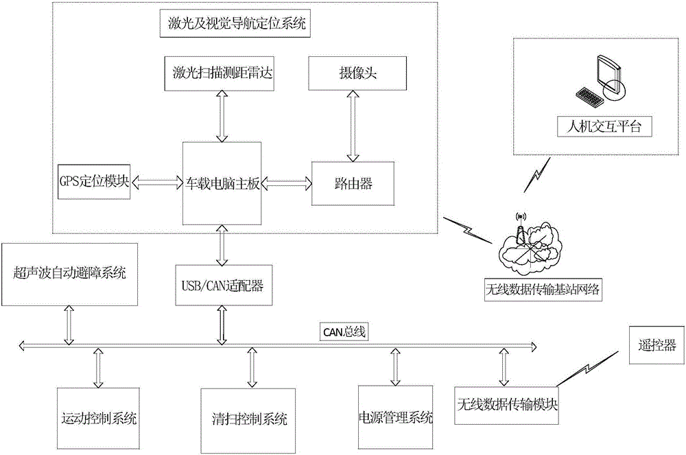
[0052] Such as figure 1 As shown, the autonomous road cleaning control system based on laser and vision described in the present invention includes the underlying control system, laser and visual navigation and positioning system, wireless data transmission base station network and human-computer interaction platform, wherein the underlying control system and laser and visual The navigation and positioning system is connected to realize data protocol conversion, and the underlying control system and laser and visual navigation and positioning system realize data communication with the human-computer interaction platform through the wireless data transmission base station network.
[0053] In order to further illustrate the above-mentioned embodiment 1, the underlying control system includes a power management system, a motion control system, an ultrasonic automatic obstacle avoidance system, and a cleaning control system. The distance sensor includes a plurality of ultrasonic ...
Embodiment 2
[0058] A method for autonomous road cleaning control based on laser and vision, comprising the following steps:
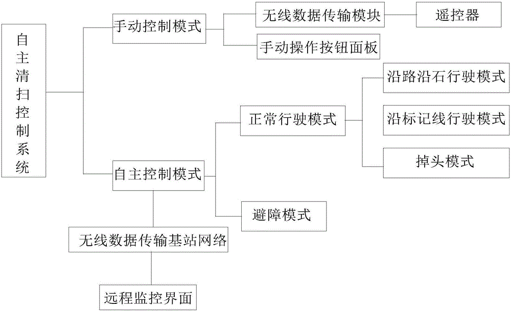
[0059] S1: The underlying control system cooperates with the laser and visual navigation and positioning system to control the corresponding sweeper to drive and clean in the normal driving mode. According to the road conditions, the data of the laser scanning ranging radar is collected to realize the driving mode along the road and the stone; the data of the camera is collected. Realize the driving mode along the marked line; collect the information of the camera and GPS positioning module to realize the U-turn mode.
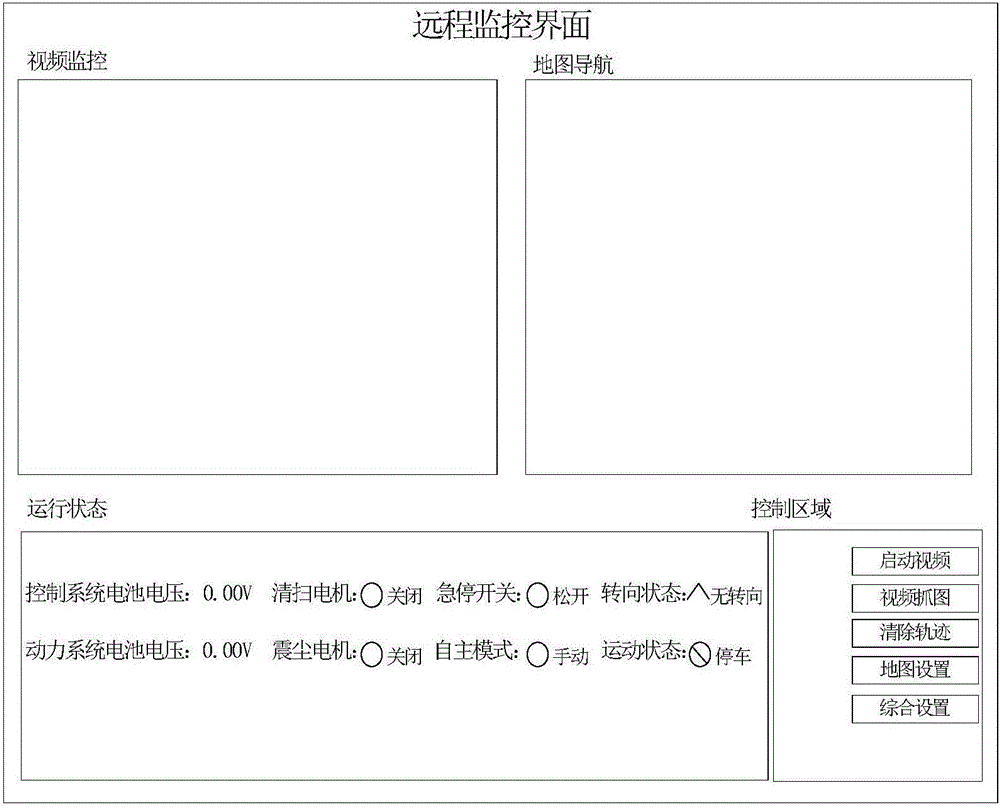
[0060] S2: According to the needs, external personnel can realize movement and cleaning actions through the remote control in the manual control mode, and carry out path planning and autonomous navigation through the laser and visual navigation and positioning system in the autonomous control mode to realize unmanned driving and automatic cleaning. ...
PUM
 Abstract
Description
Claims
Application Information