
A sludge microwave infrared coupling low temperature drying equipment

A microwave infrared and sludge technology, applied in sludge treatment, water/sludge/sewage treatment, dehydration/drying/concentrated sludge treatment, etc. Wear and tear and other problems, to reduce the risk of high-voltage electric injury, avoid burns, fast drying effect

Active Publication Date: 2018-09-25
KANGTAI JIANGSU ENVIRONMENTAL PROTECTION LTD BY SHARE LTD
View PDF3 Cites 0 Cited by
  • Summary
  • Abstract
  • Description
  • Claims
  • Application Information

AI Technical Summary

Problems solved by technology

[0003] At present, most of the sludge drying systems on the market are thermal drying. Using steam or heat transfer oil to heat and dry sludge has problems such as high energy consumption, easy wear and corrosion of equipment, especially petrochemical sludge. The volatilization of flammable and explosive gases during the process has the risk of explosion; in addition, during the thermal drying process, the paddles are constantly turning the sludge, which is easy to generate dust, which not only pollutes the environment, but also may cause a dust explosion, which is very unsafe.
[0004] There are also a small number of low-temperature drying systems in the market, which use heat pumps to absorb the heat in the environment to circulate and dry the sludge in the system, which has the advantages of energy saving and less pollution, but the humidity and temperature of the environment have a certain impact on the drying system. Moreover, the processing speed is slow and the equipment is huge, which cannot meet the needs of a large amount of sludge treatment.

Method used


Image

  • A sludge microwave infrared coupling low temperature drying equipment
  • A sludge microwave infrared coupling low temperature drying equipment

Examples


Embodiment Construction

[0024] In order to enable those skilled in the art to better understand the solution of the present invention, the present invention will be further described in detail below in conjunction with the accompanying drawings and specific embodiments.

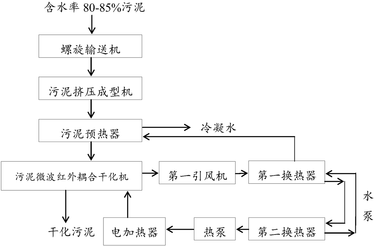
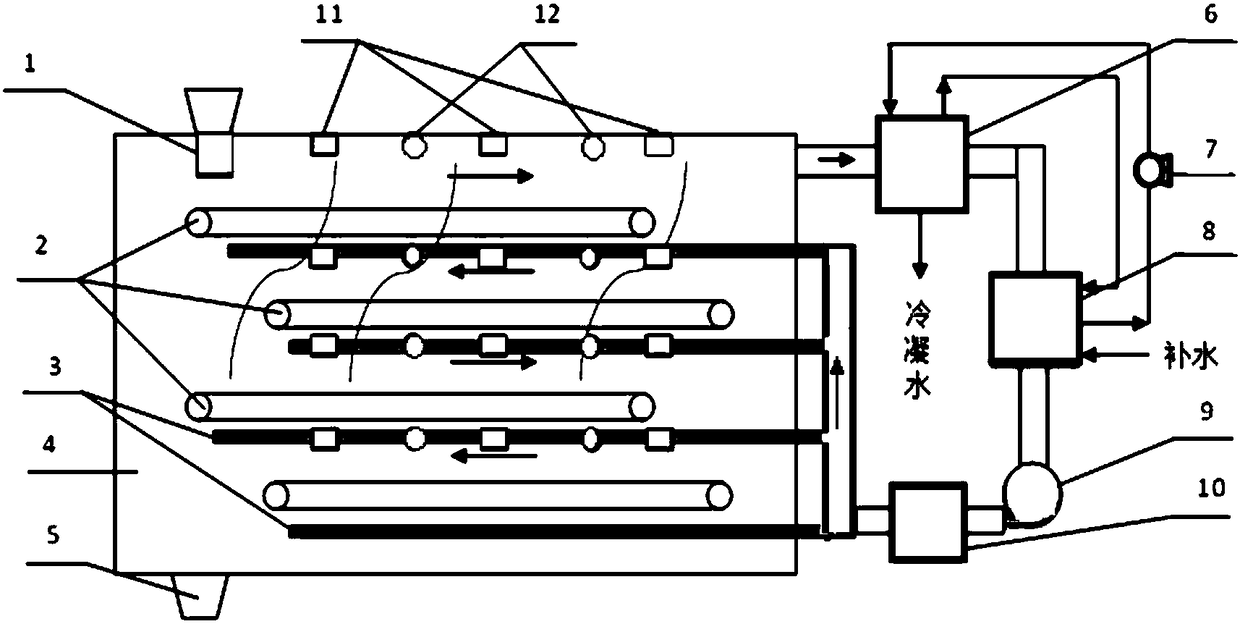
[0025] Please refer to Figure 1-2 , a sludge microwave infrared coupling low-temperature drying equipment provided by the present invention includes a screw conveyor, a sludge extrusion molding machine, a sludge preheater and a microwave infrared coupling drying device; the screw conveyor, sludge The mud extrusion molding machine, the sludge preheater and the microwave infrared coupling drying device are connected sequentially through pipelines; the microwave infrared coupling drying device includes a microwave infrared coupling drying machine, a first induced draft fan, a first heat exchanger, The second heat exchanger, heat pump, water circulation pump and electric heater, wherein the microwave infrared coupling dryer, the first ...


PUM


Abstract

The invention discloses microwave infrared coupling low-temperature drying equipment for sludge. The microwave infrared coupling low-temperature drying equipment for the sludge comprises a screw conveyer, a sludge extrusion molding machine, a sludge preheater and a microwave infrared coupling drying device, wherein the screw conveyer, the sludge extrusion molding machine, the sludge preheater and the microwave infrared coupling drying device are sequentially connected through a pipeline; the microwave infrared coupling drying device comprises a microwave infrared coupling dryer, a first induced draft fan, a first heat exchanger, a second heat exchanger, a heat pump, a water circulating pump and an electric heater; the microwave infrared coupling dryer, the first induced draft fan, the first heat exchanger, the second heat exchanger, the heat pump and the electric heater are sequentially connected through a ventilating duct; and the electric heater is also connected to the microwave infrared coupling dryer through the ventilating duct. By the system, the sludge is dried in cycle by heat energy; the operation cost is reduced; meanwhile, secondary pollution is reduced; the risk of explosion is reduced; and the system is provided with a tail gas collecting and purifying system, a flammable and explosive gas detection probe and an alarm device.

Description

technical field [0001] The invention relates to the technical field of sludge treatment, in particular to a sludge reduction equipment and treatment method. Background technique [0002] A large amount of sludge with a moisture content of 99.7-97% is produced after industrial and domestic wastewater is purified, and after dehydration by conventional sludge dewatering equipment, it becomes sludge with a moisture content of about 80-85%. According to the survey results, nearly 90% of the sludge produced by wastewater treatment stations and sewage treatment plants has not been properly reduced and recycled. The further drying of sludge is a very feasible method of sludge reduction. The further drying of this kind of pre-dehydrated sludge does not produce secondary waste gas pollution, and efficiently reduces energy consumption. a technical problem. [0003] At present, most of the sludge drying systems on the market are thermal drying. Using steam or heat transfer oil to heat...

Claims


Application Information

Patent Timeline
Patent Type & Authority Patents(China)
IPC IPC(8): C02F11/12C02F11/00
CPCC02F11/00C02F11/12C02F2303/06
Inventor 黄华贾少伟花成巍
Owner KANGTAI JIANGSU ENVIRONMENTAL PROTECTION LTD BY SHARE LTD
Learn More