
Wet type electric dust collector with pre-coagulation function

A wet electrostatic precipitator, functional technology, applied in the field of deep purification of flue gas, can solve the problem of low dust removal efficiency of ultrafine dust particles, achieve the effect of simple and light structure, stable secondary value, and improved wet removal efficiency

Inactive Publication Date: 2016-08-03
JIANGSU FUDING ENERGY SCI & TECH
View PDF7 Cites 9 Cited by
  • Summary
  • Abstract
  • Description
  • Claims
  • Application Information

AI Technical Summary

Problems solved by technology

[0005] Aiming at the low efficiency of the existing wet electrostatic precipitator for ultrafine dust particles, the present invention provides a wet electrostatic precipitator with the function of pre-condensation

Method used


Image

  • Wet type electric dust collector with pre-coagulation function
  • Wet type electric dust collector with pre-coagulation function
  • Wet type electric dust collector with pre-coagulation function

Examples


Embodiment 1

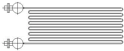
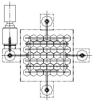
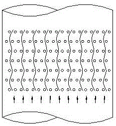
[0032] Such as figure 1 As shown, the wet electrostatic precipitator with pre-condensation function of the present invention is arranged on the top of the desulfurization absorption tower (only the top structure of the absorption tower is shown in the figure), mainly including the wet electrostatic precipitator, the condensation heat exchanger 1, and the external water tank 8 and sprinklers. The wet electrostatic precipitator is set above the condensing heat exchanger 1. The wet electrostatic precipitator is mainly composed of the cathode lower frame 2, the cathode wire 3, the cathode upper frame 4, the cathode suspension 5 and the anode assembly 7. The condensing heat exchanger 1 Installed between the outlet of the absorption tower mist eliminator and the wet electrostatic precipitator, and above the wet electrostatic precipitator and the condensing heat exchanger are respectively equipped with a flushing device, and the flushing device includes a flushing nozzle and a spray ...

Embodiment 2

[0038] The alumina catalyst used in the petroleum refining industry is manufactured by high-temperature roasting process. During the manufacturing process, a small amount of alumina powder will escape. The alumina powder cannot be charged and the particle size is less than 10 microns. The flue gas directly enters the wet electrostatic precipitator. Due to the limitation of alumina's own characteristics, the dust removal efficiency can only reach 30-50%. However, after the flue gas passes through the wet electrostatic precipitator with a condensing heat exchanger of the present invention, the temperature of the flue gas drops by 1 to 3°C, and the gas phase water condenses and precipitates into mist droplets, and the porous alumina powder condenses with it, and not only the particle size Increased to more than 40 microns, and the charging performance is improved dozens of times due to the condensed water wrapped on the surface. The condensed alumina powder particles are quickly ...


PUM

PropertyMeasurementUnit
Inscribed circle diameteraaaaaaaaaa
Lengthaaaaaaaaaa
Particle sizeaaaaaaaaaa

Abstract

The invention provides a wet electric precipitator with pre-coagulation function aiming at the deficiency that the existing wet electric precipitator has low dedusting efficiency for superfine dust particles. The wet electrostatic precipitator is arranged on the top of the desulfurization absorption tower, and mainly includes a wet electrostatic precipitator and a condensing heat exchanger. The wet electrostatic precipitator is arranged above the condensing heat exchanger. Composed of cathode suspension and anode assembly, the condensing heat exchanger is installed between the outlet of the absorption tower mist eliminator and the wet electrostatic precipitator, and the wet electrostatic precipitator and the condensing heat exchanger are respectively equipped with flushing devices. The flue gas to be treated passes through the desulfurization absorption tower, the outlet flue of the absorption tower, the phase change condensation flow equalization chamber, the wet electrostatic precipitator and the outlet flue of the dust collector in sequence from bottom to top, and then is discharged from the chimney.

Description

technical field [0001] The invention relates to a wet electrostatic precipitator process for pre-condensing fine pollutant particles below PM10 microns in wet flue gas and then entering a high-voltage electric field, which belongs to the technical field of flue gas deep purification. Background technique [0002] Fine particles below 10 microns have a large specific surface area and have strong adsorption to toxic organic pollution, heavy metals and other harmful substances. Due to their small particle size, these particles are suspended in the atmosphere and are not easy to diffuse, which has a great impact on human health and the quality of the atmospheric environment. [0003] The combustion emission source of industrial boilers is the main source of fine particulate matter below PM10. With the promulgation of the new "Emission Standard of Air Pollutants" (GB13271-2014), the concentration of soot emission from coal-fired boilers has changed from the original 50mg / m 3 Re...

Claims


Application Information

Patent Timeline
IPC IPC(8): B03C3/16B03C3/014B03C3/78B03C3/49B03C3/43
CPCB03C3/16B03C3/014B03C3/43B03C3/49B03C3/78
Inventor 裴爱芳刘坤任军民黄中华
Owner JIANGSU FUDING ENERGY SCI & TECH
Learn More