
Preparation method of ceramic material capable of generating carbon nanowires in situ

A carbon nanowire and in-situ generation technology, which is applied in the field of ceramic material preparation, can solve the problems of cumbersome carbon nanowire preparation process and high condition requirements, and achieve the effect of simple and easy to obtain raw materials, simple principle and low cost

Active Publication Date: 2016-08-17
HARBIN INST OF TECH
View PDF3 Cites 1 Cited by
  • Summary
  • Abstract
  • Description
  • Claims
  • Application Information

AI Technical Summary

Problems solved by technology

[0005] The present invention aims to solve the problems of cumbersome preparation process and high requirements for existing carbon nanowires, and provides a method for preparing ceramic materials for in-situ generation of carbon nanowires

Method used

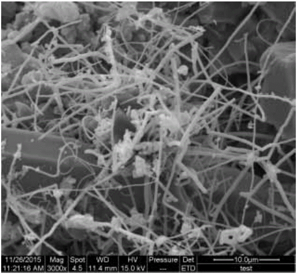
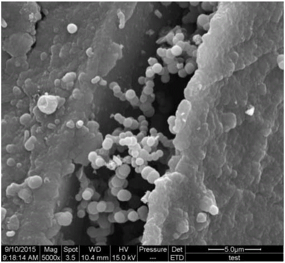
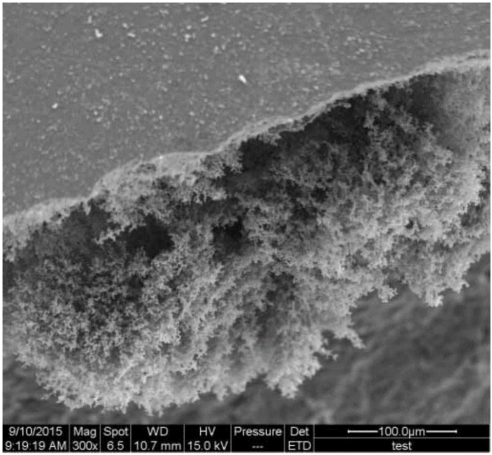

Image

  • Preparation method of ceramic material capable of generating carbon nanowires in situ
  • Preparation method of ceramic material capable of generating carbon nanowires in situ
  • Preparation method of ceramic material capable of generating carbon nanowires in situ

Examples


specific Embodiment approach 1

[0037] Specific Embodiment 1: The preparation method of the ceramic material for in-situ generation of carbon nanowires in this embodiment is carried out according to the following steps:

[0038] 1. Resin curing: Heat polysilazane or silicon aluminum carbon nitrogen precursor resin in a tube furnace filled with nitrogen at a heating rate of 1°C-5°C to 140-160°C for 4 hours, and then heat at the same heating rate To 340 ~ 360 ℃ for 20 hours to cure cross-linking;

[0039] 2. Ball milling: place the resin cross-linked in step 1 in a ball milling tank for ball milling, then pass through a 60-mesh standard sieve to obtain a powder;

[0040] 3. Pre-press molding: Pre-press the powder into a block with a diameter of Ф12.5-20mm and a thickness of 4-7mm at room temperature, with a pressure of 10-18MPa and a pre-press time of 5-8min;

[0041] 4. Pyrolysis: heating and cracking in a tube furnace under the protection of nitrogen to obtain samples;

[0042] 5. Cooling: Cool the sample ...

specific Embodiment approach 2

[0044] Specific embodiment two: the difference between this embodiment and specific embodiment one is: the preparation method of the silicon aluminum carbon nitrogen precursor resin described in step one is:

[0045] Dissolve polysilazane in xylene, weigh aluminum isopropoxide according to the mass ratio of polysilazane to aluminum isopropoxide 1: (0.05-0.20), dissolve in xylene, and ultrasonically vibrate for 15 minutes; The xylene solution of polysilazane and aluminum isopropoxide was placed in a glove box protected by an inert gas, and the temperature was raised to 120° C. to react for 24 hours to obtain a silicon aluminum carbon nitrogen precursor resin. Others are the same as in the first embodiment.

specific Embodiment approach 3

[0046] Embodiment 3: This embodiment is different from Embodiment 1 or 2 in that: the ball milling in step 2 is placed in a high-energy ball mill for 30-40 minutes or placed in a planetary ball mill for 24-26 hours. Others are the same as in the first or second embodiment.


PUM


Abstract

The invention relates to a preparation method of a ceramic material, particularly a preparation method of a ceramic material capable of generating carbon nanowires in situ. The method aims to solve the problems of high complexity and high condition requirements in the existing carbon nanowire preparation technique. The method 1 comprises the following steps: 1. carrying out resin solidification; 2. carrying out ball milling to obtain powder; 3. carrying out pre-press forming; 4. carrying out pyrolytic cracking; and 5. cooling to obtain the in-situ-generated carbon nanowire ceramic material. The method 2 comprises the following steps: 1. carrying out resin solidification; 2. carrying out ball milling to obtain powder; 3. carrying out hot-press forming; and 4. cooling to obtain the in-situ-generated carbon nanowire ceramic material. The method is simple and convenient, does not need complicated equipment or experimental steps, is low in cost, and can perform carbon nanowire in-situ generation inside the ceramic material. The method can promote the conductivity of the material. The method is applicable to the field of ceramic materials.

Description

technical field [0001] The present invention relates to a preparation method of a ceramic material. Background technique [0002] Nanowire materials belong to the microscopic category of nanometer scale in the radial direction, and can reach the macroscale category of micron or even centimeter level in the axial direction, and are considered to be the link connecting the microcosmic and macroscopic. This characteristic of nanowires gives it unique advantages in the assembly and in situ characterization of nanodevices that other nanomaterials (such as nanoparticles) do not have. [0003] One-dimensional carbon nanofibers have distinctive characteristics in many aspects such as crystallinity, orientation, electrical conductivity, thermal conductivity, density, modulus, strength, thermal stability, and specific surface area. Due to its unique chemical and physical properties, carbon nanowire materials can be widely used in composite materials, electrode materials, hydrogen sto...

Claims


Application Information

Patent Timeline
Patent Type & Authority Applications(China)
IPC IPC(8): C04B35/589C04B35/593C04B35/58C04B35/80
CPCC04B35/58021C04B35/589C04B35/593C04B35/806C04B2235/5248
Inventor 李金平侯一心孟松鹤杨程牛加宏胡兆财
Owner HARBIN INST OF TECH
Learn More