Direct contact type flue gas waste heat recovery device

A flue gas waste heat recovery device technology, applied in direct contact heat exchangers, heat exchange equipment, heat exchanger types, etc., can solve the problems of large flue gas side resistance, weakened heat exchange capacity, and large flue gas resistance. , to achieve the effect of improving heat exchange efficiency, reducing resistance and ensuring heat exchange effect

Active Publication Date: 2016-08-17
YANTAI EBARA AIR CONDITIONER
View PDF8 Cites 8 Cited by
  • Summary
  • Abstract
  • Description
  • Claims
  • Application Information

AI Technical Summary

Problems solved by technology

Although the heat exchange effect of this method is better, but the spray volume is large, and a considerable part of the droplets will offset each other due to the spraying, and directly fall into the bottom, the residence time is short, the heat exchange performance is attenuated, and the production and operation costs are high. higher
[0006] The second category, such as the "centralized heating system using absorption heat pump to recover flue gas waste heat" disclosed in Chinese patent 201110110470.X, this system uses cold water produced by absorption heat pump to spray in the spray tower to recover flue gas waste heat, However, water and flue gas are in a reverse flow relationship, resulting in greater resistance on the side of the flue gas
[0008] In summary, the existing flue gas-water direct contact spraying device, or the flue gas-water crossing double-sided spraying method, has a large spray volume and inevitably has some liquid droplets offset to weaken the heat transfer capacity; Or use the flue gas-water countercurrent spraying method, resulting in greater resistance to the flue gas; or use the upward or downward spraying method, the spraying height is limited due to upward spraying, and the droplet residence time is short due to downward spraying

Method used


Image

  • Direct contact type flue gas waste heat recovery device
  • Direct contact type flue gas waste heat recovery device
  • Direct contact type flue gas waste heat recovery device

Examples


Embodiment Construction

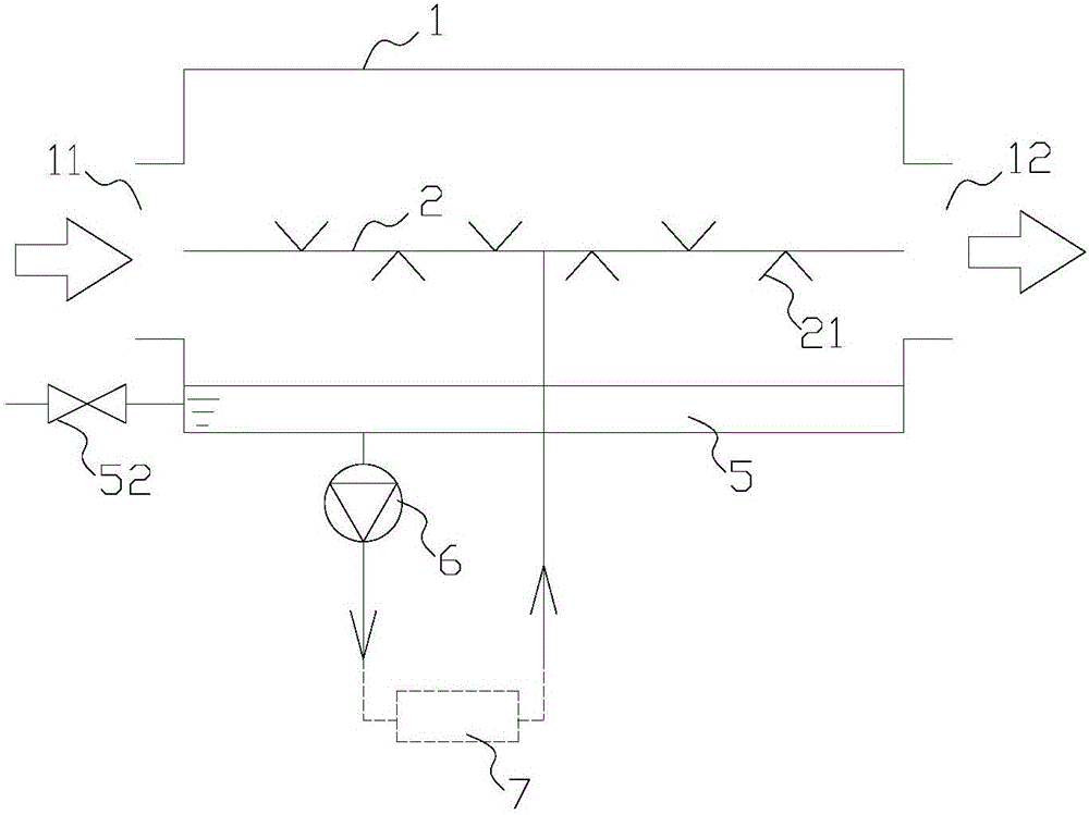
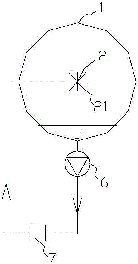
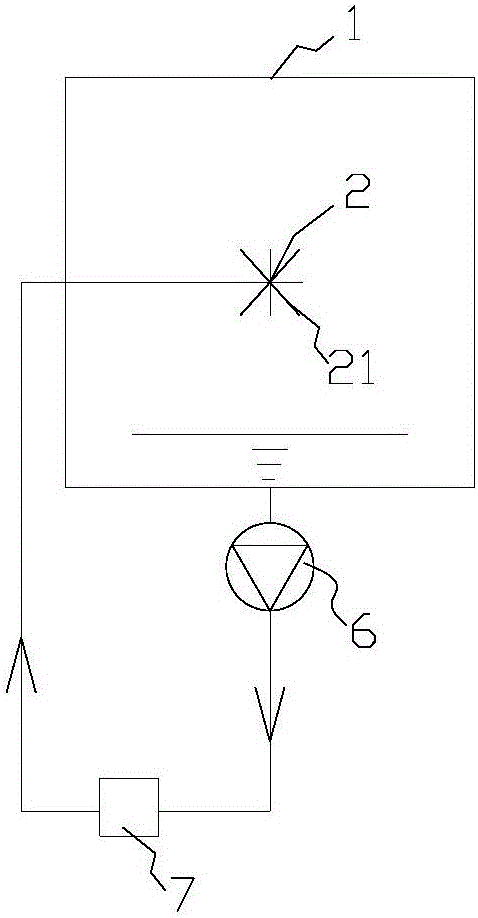
[0052] The core of the present invention is to provide a direct contact flue gas waste heat recovery device, which can not only reduce the collision loss of liquid droplets, reduce the resistance of flue gas, but also reduce the influence of gravity acceleration, prolong the residence time of liquid droplets, improve Mass and heat transfer capabilities, thereby improving the efficiency of flue gas recovery.

[0053]In order to enable those skilled in the art to better understand the technical solutions of the present invention, the present invention will be further described in detail below in conjunction with the accompanying drawings and specific embodiments.

[0054] It should be noted that the orientation words "horizontal, vertical, up, down, left, and right" appearing in this article are all established based on the drawings in the specification, and their appearance should not affect the scope of protection of the present invention.

[0055] In a specific embodiment, th...


PUM


Abstract

The invention discloses a direct contact type flue gas waste heat recovery device. The direct contact type flue gas waste heat recovery device comprises a recovery tower. The recovery tower is provided with a smoke inlet and a smoke outlet for flue gas to flow, and is further provided with a main spraying pipe used for spraying cooling water, and a plurality of spraying nozzles arranged on the main spraying pipe. The main spraying pipe is arranged along the axis of the recovery tower; the spraying nozzles spray cooling water around in a radial mode in the spraying direction, and the connecting line of the flue gas inlet and the flue gas outlet intersects with the spraying direction of the spraying nozzles. By the adoption of the structure, the collision loss of droplets can be reduced, the flue gas resistance can be reduced, the influence of gravitational acceleration can be reduced, the staying time of droplets can be prolonged, the mass and heat transfer capacity can be improved, and thus the flue gas recovery efficiency can be improved.

Description

technical field [0001] The invention relates to the technical field of energy utilization, in particular to a direct contact flue gas waste heat recovery device. Background technique [0002] The flue gas finally discharged after combustion of natural gas and other gases contains a large amount of water vapor, which accounts for about 10% of the total heat (high calorific value) of natural gas. At present, these heats are basically not used but directly discharged into the atmosphere. If this part of the latent heat of vaporization is recovered, the heat exchange efficiency of the equipment or system can be greatly improved, the consumption of natural gas can be reduced, and it is beneficial to realize energy saving and emission reduction. [0003] Flue gas waste heat recovery devices can be divided into indirect contact type and direct contact type. The indirect contact type is small in size, but due to the influence of the thermal resistance of the contact surface, the he...

Claims


Application Information

Patent Timeline
Patent Type & Authority Applications(China)
IPC IPC(8): F28C3/08F28F19/00
CPCF28C3/08F28F19/00
Inventor 吕林昌陈瑞杏刘晶彭小磊李绍飞邵泽艳林富春
Owner YANTAI EBARA AIR CONDITIONER
Why Eureka
Try Eureka