Array antenna for generating microwave orbital angular momentum based on phase gradient super-surface

An orbital angular momentum, array antenna technology, applied in the field of communication, can solve the problems of unsuitable use on satellite, complex structure, difficult manufacturing process, etc., and achieve the effect of reducing attenuation rate, improving reflection effect, improving vortex effect and reflection efficiency

Active Publication Date: 2016-08-17
SUNWAVE COMM
View PDF2 Cites 42 Cited by
  • Summary
  • Abstract
  • Description
  • Claims
  • Application Information

AI Technical Summary

Problems solved by technology

However, this method is also limited by the resolution and energy threshold of the spatial light modulator, and cannot handle high-power laser beams.
[0007] The problem existing in the above disclosed prior art is that the current research is mainly focused on using the orbital angular momentum of the laser for communication, the spiral phase plate method, the phase holography method, the mode converter method composed of cylindrical lenses, etc. to generate vortex beams. The implementation of the method is relatively complicated, and in the realization of beam orbital angular momentum state multiplexing, many devices are used, the structure is complex, and it is not easy to be small and integrated, so it is not suitable for satellite use
Moreover, optical communication technology also has many restrictions on the transmission environment. For example, the laser satellite-ground link is much more affected by the rainfall, smoke and fog in the atmosphere than microwave
[0008] In view of the fact that the above methods are to generate vortex beams in the light wave frequency band, although it is feasible, there are problems such as complex system structure, difficult manufacturing process, small diffraction angle, and low diffraction efficiency.
In the microwave frequency band, since the wavelength reaches the order of millimeters or even centimeters, it is difficult to tailor the phase in a small volume space, which restricts its application in the field of microwave communication.

Method used


Image

  • Array antenna for generating microwave orbital angular momentum based on phase gradient super-surface
  • Array antenna for generating microwave orbital angular momentum based on phase gradient super-surface
  • Array antenna for generating microwave orbital angular momentum based on phase gradient super-surface

Examples


Embodiment

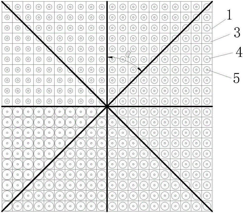
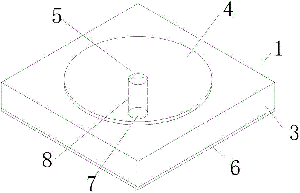
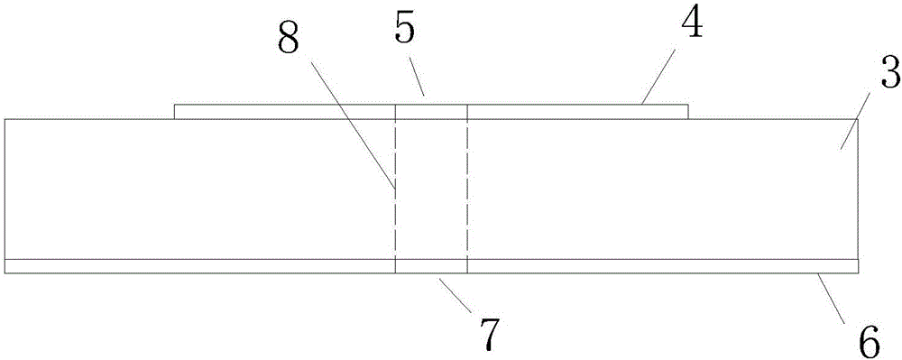
[0029] Embodiment: a kind of array antenna based on phase gradient metasurface to produce microwave orbital angular momentum, as attached Figure 1-3 As shown, it includes an array antenna 2 spliced ​​into a whole by a phase shifting unit 1. The phase shifting unit 1 includes a square dielectric plate 3. The surface of the dielectric plate 3 is provided with a circular metal patch 4. The middle of the metal patch 4 is provided with an upper Holes 5; a square metal grounding plate 6 is provided at the bottom of the dielectric plate 3, and the dimensions of the dielectric plate and the metal grounding plate are the same. A lower hole 7 is provided in the middle of the metal grounding plate 6 ; a metal pipe 8 is provided in the middle of the dielectric plate 3 , and the metal pipe 8 communicates with the upper hole 5 and the lower hole 7 .

[0030] In order to realize the uniform and continuous control of the orbital angular momentum of the incident wave from 0 to 2π phase, the p...


PUM


Abstract

The invention discloses an array antenna for generating microwave orbital angular momentum based on a phase gradient super-surface. The array antenna is formed by the arrangement of phase shift units (1), each phase shift unit (1) comprises a dielectric plate (3), a metal patch (4) is arranged on the surface of the dielectric plate (3), an upper hole (5) is formed in the middle of the metal patch (4), a metal ground plate (6) is arranged at the bottom of the dielectric plate (3), a lower hole (7) is formed in the middle of the metal ground plate (6), and a metal pipe (8) is arranged at the middle of the dielectric plate (3) and communicates with the upper hole (5) and the lower hole (7). The array antenna has the characteristics of small size, light weight and low cost; meanwhile, the continuous control of the orbital angular momentum in phases of 0 to 2Pi is further achieved, and obvious vortex orbital angular momentum is generated; and moreover, the array antenna has an excellent reflection effect.

Description

technical field [0001] The invention relates to an array antenna for generating microwave orbital angular momentum based on a phase gradient metasurface, belonging to the communication field. Background technique [0002] As an important physical quantity in physics, orbital angular momentum (OAM) has rapidly promoted the new development of nonlinear optics, quantum optics, atomic optics and astronomy since it was confirmed by Allen et al. in 1992. Different from the spin angular momentum, the orbital angular momentum is associated with the helical phase wave front, which can theoretically take infinite values ​​and be orthogonal to each other. In the interdisciplinary field of physics and optical communication, scientists have introduced orbital angular momentum into optical communication, which is similar to degrees of freedom such as wavelength, time slot and polarization, and regarded orbital angular momentum as a new degree of freedom and as a data information carrier, ...

Claims


Application Information

Patent Timeline
Patent Type & Authority Applications(China)
IPC IPC(8): H01Q1/36H01Q1/50H01Q3/30
CPCH01Q1/36H01Q1/50H01Q3/30
Inventor 徐弼军
Owner SUNWAVE COMM
Why Eureka
Try Eureka