Tail wing pouring system and tail wing manufacturing method for aluminum alloy underwater launching tube

An underwater launch and pouring system technology, applied in the field of pressure-resistant sealed container manufacturing, can solve the problems of low material utilization, high cost of forged castings, and difficult control of deformation, so as to improve internal quality and compactness, and ensure shape and size Good effect of precision, stability and shock resistance

Active Publication Date: 2016-08-24
HUBEI SANJIANG AEROSPACE WANFENG TECH DEV
View PDF6 Cites 4 Cited by
  • Summary
  • Abstract
  • Description
  • Claims
  • Application Information

AI Technical Summary

Problems solved by technology

[0004] At present, the sheet metal roll welding forming process adopted by the cylinder body requires the ribs in the inner cavity and the mounting bosses to be welded to the cylinder wall one by one after rolling welding. There are many welds, and the deformation is not easy to control. The stability and shock resistance Poor; in addition, due to the small internal space, the operation is inconvenient, and there are certain safety hazards; at the same time, there are certain dimensional errors between the inner cavity reinforcement rib, the installation boss and the cylinder wall, which cannot be completely fitted, which affects the strength of the cylinder and stability; in addition, the corrosion resistance of the weld position is poor
[0005] At present, the cylinder adopts the forging machining forming process, and its internal cavity reinforcement ribs and mounting bosses can only be formed by processing, which has low material utilization rate and high processing cost; forged castings have high cost and long processing cycle; the length of one forging is limited, Generally, after segmental forging, butt welding or screw connection is required to form a cylinder with a required length. The process is more and more complicated, the deformation is diffic

Method used


Image

  • Tail wing pouring system and tail wing manufacturing method for aluminum alloy underwater launching tube
  • Tail wing pouring system and tail wing manufacturing method for aluminum alloy underwater launching tube
  • Tail wing pouring system and tail wing manufacturing method for aluminum alloy underwater launching tube

Examples


Example Embodiment

[0030] Below in conjunction with accompanying drawing and specific embodiment the present invention is described in further detail:

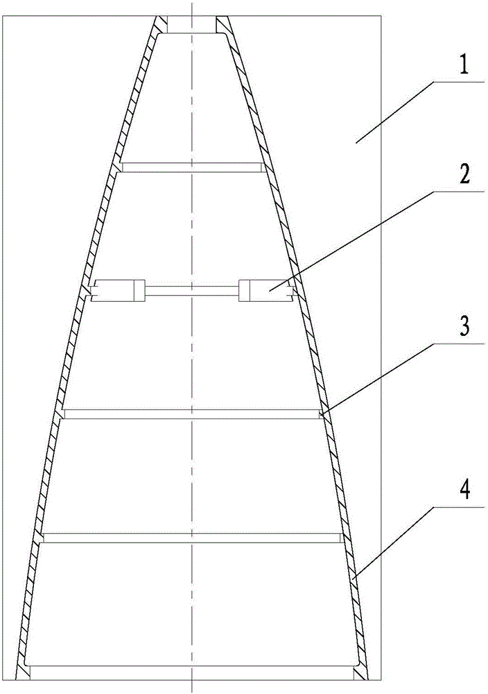
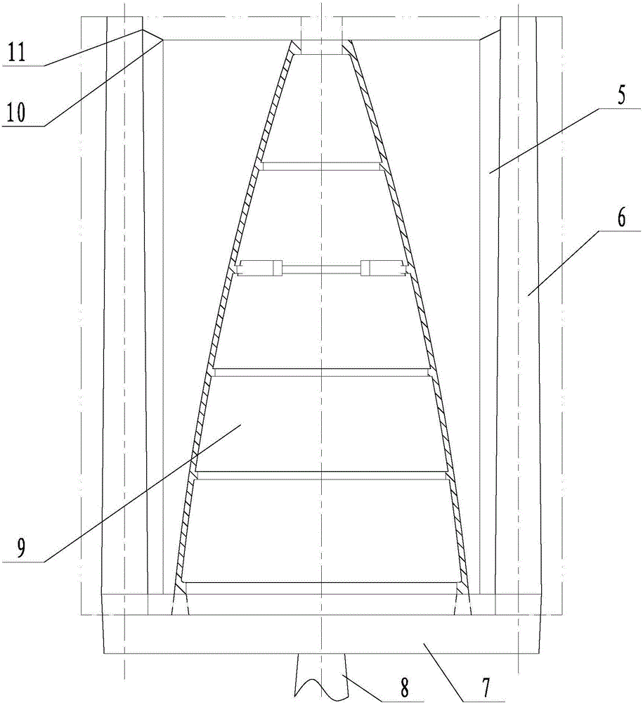
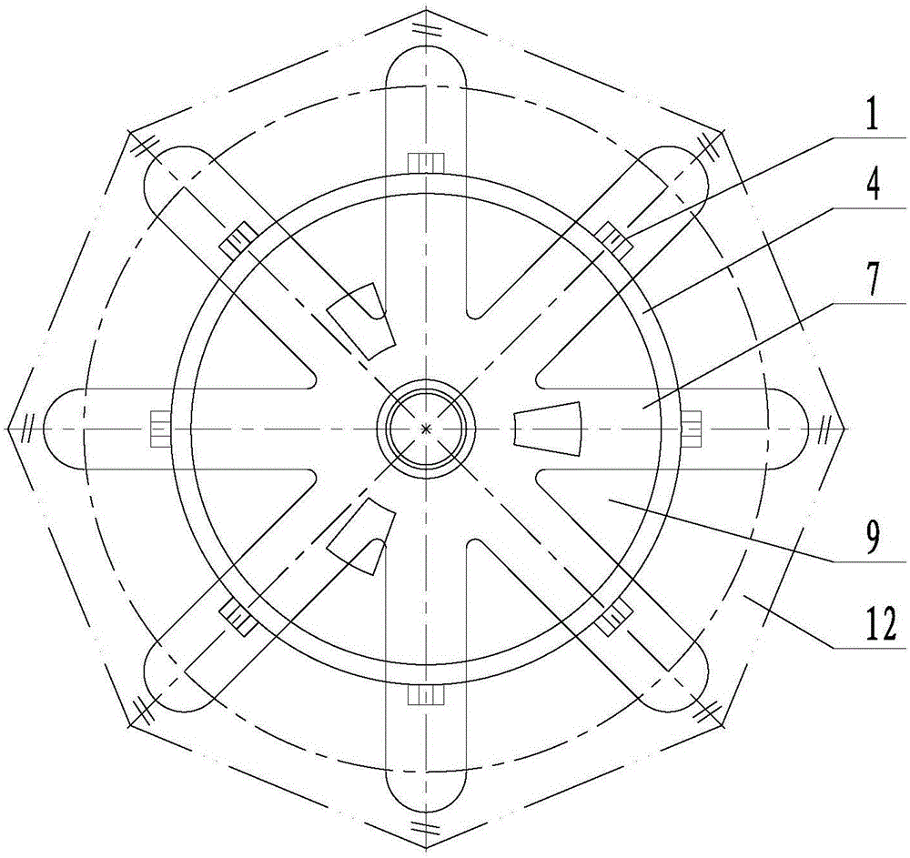
[0031] like Figure 1~4 The aluminum alloy underwater launching tube empennage pouring system includes a runner 7, a sprue 8, and a plurality of vertical tubes 6 corresponding to the wings 1 in the underwater launching tube empennage casting, and the runner 7 and the sprue 8 are all located at the bottom of the vertical tube 6, the sprue 8 communicates with the runner 7, the runner 7 communicates with the bottom of each vertical tube 6, and the empennage castings of the underwater launching tube are located at all Inside the cylindrical area surrounded by the vertical tube 6, there is a gap 5 between the empennage casting of the underwater launching tube and the outer side wall of each vertical tube 6, and the top of each vertical tube 6 communicates with the corresponding gap 5, and the water The inner cavity of the lower launching tube empenn...


PUM


Abstract

The invention discloses a tail wing pouring system for an aluminum alloy underwater launching tube. According to the tail wing pouring system, a horizontal runner and a vertical runner are located on the bottoms of vertical cylinders and communicate with each other, and the horizontal runner communicates with the bottoms of the vertical cylinders; a tail wing casting of the underwater launching tube is located inside the cylindrical area defined by the vertical cylinders and is spaced from the outer side wall of each vertical cylinder by a gap, the top of each vertical cylinder communicates with the corresponding gap, a cavity of the tail wing casting of the underwater launching tube is formed by an inner sand core, and an outline and wings of the tail wing casting of the underwater launching tube, the vertical cylinders and the gaps are formed by outer sand cores. According to the system, the tail wings high in overall strength, water tightness, stability, earthquake resistance, corrosion resistance and dimensional accuracy can be provided; the method has the advantages that the process is simple, the operation is convenient and the manufacturing cost is low.

Description

technical field [0001] The invention relates to the technical field of pressure-resistant sealed containers, in particular to an aluminum alloy underwater launch tube empennage pouring system and an empennage manufacturing method. Background technique [0002] Underwater launch tube, as a pressure-resistant cabin working in an underwater environment, in order to meet the underwater launch depth and navigation maneuverability requirements of the launch tube, its structure and connections need to meet the two basic requirements of pressure resistance and watertightness, and at the same time pursue as much as possible The minimum structural weight (thin, light and high strength), and has a certain corrosion resistance. The aluminum alloy material itself has a certain corrosion resistance. After the surface is painted or oxidized, it has good corrosion resistance and high strength. Therefore, the current underwater launch tube is generally made of aluminum alloy. [0003] The e...

Claims


Application Information

Patent Timeline
IPC IPC(8): B22D18/04C22C21/02
CPCB22D18/04C22C21/02
Inventor 王德清史勇陈辉尹家新李洪平刘杰苏鹏
Owner HUBEI SANJIANG AEROSPACE WANFENG TECH DEV
Why Eureka
Try Eureka