Device and method for preparing reducing gas through lignite gasification poly-generation

A technology of coal gasification and polygeneration, applied in the metallurgical field, can solve the problems of high gasifier pressure, high gas production cost, and harsh raw material requirements.

Active Publication Date: 2016-08-24
CERI ENERGY & AIR PROTECTION TECH CO LTD +1
View PDF7 Cites 8 Cited by
  • Summary
  • Abstract
  • Description
  • Claims
  • Application Information

AI Technical Summary

Problems solved by technology

[0004] None of the existing coal gasification processes can directly provide gas components that meet the requirements, and a conversion device is needed to adjust the gas compo

Method used


Image

  • Device and method for preparing reducing gas through lignite gasification poly-generation
  • Device and method for preparing reducing gas through lignite gasification poly-generation

Examples


Embodiment 1

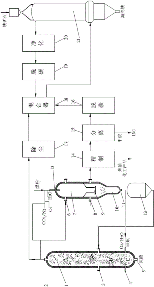
[0076] This embodiment provides a device for producing reducing gas by lignite gasification polygeneration, and its schematic diagram is as follows figure 1As shown, the device includes a gasifier 1, a pyrolysis / partial gasifier 7, a semi-coke storage tank 12, a dust removal unit 17 and a mixer 18; wherein:

[0077] The gasifier 1 is divided into a first reaction zone A, a second reaction zone B and a third reaction zone C from top to bottom;

[0078] A catalyst inlet 3 is provided between the first reaction zone and the second reaction zone;

[0079] A semi-coke / gasifying agent inlet 4 is provided between the second reaction zone and the third reaction zone;

[0080] The top and the bottom of the gasifier are respectively provided with a synthesis gas outlet 2 and an ash outlet 5;

[0081] The furnace of the pyrolysis / partial gasification furnace 7 is provided with a guide tube 9, and the guide tube 9 divides the pyrolysis / partial gasification furnace 7 into a pyrolysis / par...

Embodiment 2

[0090] This example uses figure 1 The device shown implements the method for producing reducing gas by lignite gasification polygeneration. After the lignite is crushed, it is ground and sieved to obtain coal powder below 0.1mm, and the gasification agent (H 2 O, O 2 ), and inert gas (N 2 and CO 2 ) or synthesis gas (wherein the mass ratio of oxygen to lignite is 0.2:1, the mass ratio of water vapor to lignite is 0.6:1, and the mass ratio of inert gas to lignite is 0.2:1), and enters the pyrolysis / partial gas through nozzle 13 The chemical furnace 7 is mixed with the high-temperature syngas entering the heat carrier inlet 6 to undergo pyrolysis / partial gasification reaction at a reaction temperature of 850°C to generate CO and H 2 、CH 4 etc. Gas, tar and solid semi-coke; volatiles and semi-coke enter the lower part of the furnace body along the guide tube for separation, volatiles are discharged from the volatiles outlet 8 and enter the refining unit 14; semi-coke falls in...

Embodiment 3

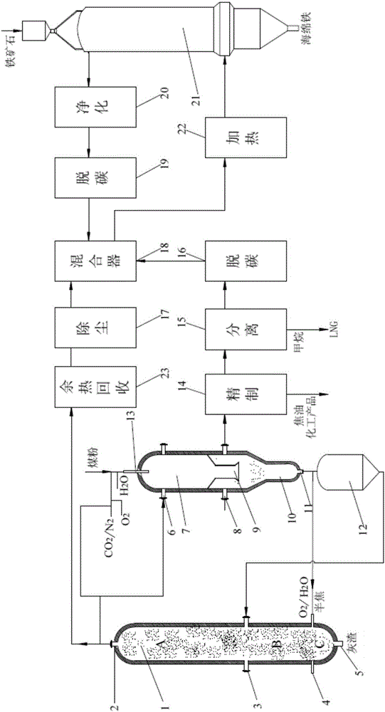
[0092] This example provides figure 2 shown in the device, the device is in figure 1 On the basis of that, a waste heat recovery device 23 is added before the dust removal unit 17, and a heating device 22 is added on the pipeline for transporting reducing gas.

[0093] This example uses figure 2 The device shown implements the method for producing reducing gas by lignite gasification polygeneration, and its method is the same as that of Example 1, except that before the syngas is carried out in the dust removal unit 17, it first enters the waste heat recovery device to recover the sensible heat of the coal gas, and then Enter the mixer 18 through the dust removal unit 17; after the pyrolysis gas, furnace top gas, and synthesis gas entering the mixer 18 are mixed, when the temperature of the output reducing gas is low, add a gas heater in front of the shaft furnace to increase the temperature of the reducing gas. temperature to 900°C.


PUM


Abstract

The invention provides a device and method for preparing reducing gas through lignite gasification poly-generation. The device comprises a gasification furnace, a pyrolysis or partial gasification furnace, a semi-coke storage tank, a dust removal unit and a mixer; the gasification furnace is divided into a first area, a second area and a third area, a catalyst inlet is formed between the first area and the second area, a semi-coke or gasification agent inlet is formed between the second area and the third area, and the top end and the bottom end of the gasification furnace are provided with a synthesis gas outlet and an ash slag outlet respectively; a guide cylinder is arranged in the pyrolysis or partial gasification furnace, the top end and the bottom end of the pyrolysis or partial gasification furnace are provided with a nozzle and a semi-coke outlet respectively, the portion, close to the top end, of the pyrolysis or partial gasification furnace is provided with a heat carrier inlet, and a volatile matter outlet is formed in a semi-coke storage bin; the semi-coke outlet is connected with an inlet of the semi-coke storage tank and the semi-coke or gasification agent inlet; the synthesis gas outlet is connected with the heat carrier inlet and further connected with a mixer inlet through the dust removal unit; the volatile matter outlet is connected with the mixer inlet; the mixer inlet is further sequentially connected with a top gas decarbonization unit and a top gas purification unit. The method is achieved through the device, lignite can be transformed in a classifying mode to produce the reducing gas, the cost is low, the heat efficiency is high, and environment friendliness is achieved.

Description

technical field [0001] The invention relates to a device and a method for producing reducing gas through lignite gasification polygeneration, belonging to the technical field of metallurgy. Background technique [0002] Direct reduction ironmaking is a process that uses coal, gas or liquid fuels as energy sources and reducing agents to obtain solid direct reduced iron by reducing iron oxide in iron ore without melting below the softening temperature of iron ore. This process does not use coke. It does not need sintered ore, and has the characteristics of high quality, low consumption and low pollution. Among them, the shaft furnace gas-based direct reduction ironmaking technology is a new non-blast furnace ironmaking technology developed in the past two decades. It relies on high-quality natural gas resources and high-grade ore resources, and has been well received abroad in recent years. However, it has not been well developed and applied in my country, which is mainly rest...

Claims


Application Information

Patent Timeline
IPC IPC(8): C10J3/66C10J3/62C10J3/86C10J3/84C10J3/48C10J3/46C10J3/72C21B13/02
CPCC10J3/46C10J3/48C10J3/62C10J3/66C10J3/721C10J3/723C10J3/84C10J3/86C10J2300/0906C10J2300/093C10J2300/0959C10J2300/0976C10J2300/0986C10J2300/16C10J2300/1603C10J2300/1618C10J2300/164C21B13/0073C21B13/02Y02P20/10
Inventor 杨伟明孙加亮赵红刘红娟吴英军刘丰叶小虎李晓翔
Owner CERI ENERGY & AIR PROTECTION TECH CO LTD
Why Eureka
Try Eureka