Two-stage series pressurization direct-driven centrifugal air compressor of fuel cell engine

A technology of centrifugal air compressors and fuel cells, which is applied in liquid fuel engines, engine components, machines/engines, etc., can solve the problems of rotor-spindle speed reduction, support component damage, and increased friction loss, etc., to avoid gears Effects of meshing vibration noise, avoiding accuracy changes, and suppressing axial movement

Active Publication Date: 2016-08-24
TONGJI UNIV
View PDF10 Cites 21 Cited by
  • Summary
  • Abstract
  • Description
  • Claims
  • Application Information

AI Technical Summary

Problems solved by technology

[0007] In addition, the electrochemical reaction of the fuel cell is carried out under certain temperature, humidity and gas pressure, and the reaction is accompanied by the release of certain heat. Therefore, the air in the air supply system of the fuel cell engine has high temperature and high humidity. , high pressure, large flow and oil-free characteristics, the intervention of oil will reduce the catalytic effect of the fuel cell catalyst and greatly reduce the power output of the fuel cell engine
[0008] At the same time, in order to increase the pressure and flow of the output air, the centrifugal air compressor often adopts the speed control method of ultra-high speed (above 50,000 Rpm). The existing traditional rolling and sliding oil-lubricated bearings are difficult to meet the requirements. First, It

Method used


Image

  • Two-stage series pressurization direct-driven centrifugal air compressor of fuel cell engine
  • Two-stage series pressurization direct-driven centrifugal air compressor of fuel cell engine
  • Two-stage series pressurization direct-driven centrifugal air compressor of fuel cell engine

Examples


Example Embodiment

[0038] Example

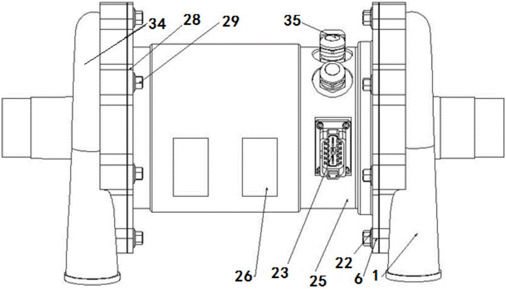
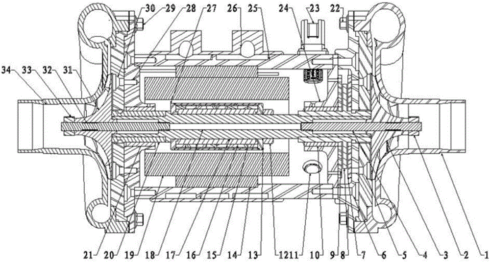
[0039] A high-power (10kW) high-speed (50000rpm) high-speed two-stage series supercharged direct-drive centrifugal air compressor that meets the full working conditions of vehicle fuel cell engine. Its structure is as follows figure 1 with figure 2 As shown, the air compressor is driven by a motor to rotate. The air compressor is provided with a left end volute 34 and a right end volute 1. The left end volute 34 is provided with an air inlet, an air outlet, and a left end volute cover 30, and a right end volute 1 An air inlet, an air outlet, and a right volute end cover 5 are provided on the upper part. During operation, the air outlet of the left volute 34 is connected to the air inlet of the right volute 1. The left and right sides of the air compressor are also provided with a left end motor end cover 28 and a right end motor end cover 6, the left end volute end cover 30 and the left end motor end cover 28 are connected and fixed by the left end connecting bol...


PUM


Abstract

The invention relates to a two-stage series pressurization direct-driven centrifugal air compressor of a fuel cell engine. The two-stage series pressurization direct-driven centrifugal air compressor comprises end covers, a spindle, volutes, impellers, a rotor, a stator and a driver. The spindle is supported by a left-end radial supporting air foil bearing, a left-end radial supporting air foil bearing bush, an air foil axial thrust bearing and a right-end radial supporting air foil bearing, wherein the left-end radial supporting air foil bearing and the left-end radial supporting air foil bearing bush are arranged on the left side, and the air foil axial thrust bearing and the right-end radial supporting air foil bearing are arranged on the right side of the spindle. The left-end radial supporting air foil bearing bush is arranged on the outer side of the spindle in a surrounding manner. The left-end radial supporting air foil bearing is fixed to the outer side of the left-end radial supporting air foil bearing bush. The air foil axial thrust bearing is fixed to the outer side of the spindle in a bush form. The right-end radial supporting air foil bearing is fixed to the outer side of the air foil axial thrust bearing. Compared with the prior art, the two-stage series pressurization direct-driven centrifugal air compressor is more suitable for the air inlet pressurization scene of the fuel cell engine with the high oilless air inlet requirement, and the durability and reliability of the air compressor of the fuel cell engine can be improved.

Description

technical field [0001] The invention relates to the technical field of fuel cell engines, in particular to a two-stage serial supercharged direct-drive centrifugal air compressor for a fuel cell engine. Background technique [0002] Recently, severe smog and haze pollution have occurred frequently in many cities in my country, making people aware of the seriousness of air pollution again. The increasingly severe energy and environmental challenges have made the transformation of transportation energy and power a global consensus. The development of new energy fuel cell vehicles is considered to be an important part of the transformation of transportation energy and power, and has attracted much attention. Proton exchange membrane fuel cell is the most mature representative of the current fuel cell family. It is a device that uses hydrogen and air (oxygen in the air) as fuel to undergo an electrochemical reaction, and converts the chemical energy of the fuel directly into el...

Claims


Application Information

Patent Timeline
IPC IPC(8): F04D25/08F04D25/16F04D29/056F04D29/051F04D29/053F04D29/58F04D29/26H02K1/28H02K1/27H02K11/20
CPCH02K1/2706H02K1/28F04D25/08F04D25/163F04D29/051F04D29/053F04D29/056F04D29/266F04D29/5806F16C17/042F16C17/024F04D29/057F04D17/122F04D29/0513F16C2360/44
Inventor 张智明章桐王心坚许思传温立军
Owner TONGJI UNIV
Why Eureka
Try Eureka