Energy-saving gas washing process

A gas washing, energy-saving technology, applied in the separation of dispersed particles, chemical instruments and methods, separation methods, etc., can solve the problems of low recovery rate of low-temperature methanol washing device, increase of methanol circulation, affecting absorption effect, etc. The effect of saving cooling capacity, reducing circulation, and improving CO2 recovery rate

Active Publication Date: 2016-09-07
SINOPEC NINGBO ENG +2
View PDF8 Cites 17 Cited by
  • Summary
  • Abstract
  • Description
  • Claims
  • Application Information

AI Technical Summary

Problems solved by technology

[0002] The existing low-temperature methanol washing technology generally uses low-pressure nitrogen stripping to remove CO in low-pressure sulfur-rich methanol. 2 The gas is decomposed to realize the H 2 The enrichment of S will make a lot of CO 2 The gas enters the vent tail gas, resulting in CO 2 Low recovery rate
At the same time, when the semi-lean liquid process is adopted, carbon-rich methanol is flashed at low pressure to recover CO 2 The latter part of the liquid phase of the gas is sent to the absorption tower as the main wash methanol, and the low-pressure flash is limited by the flash temperature and flash pressure, and the CO in the main wash methanol returned to the absorption tower 2 If the content is too high, it will affect the absorption effect, resulting in an increase in the methanol circulation required by the device and an increase in energy consumption

Method used


Image

  • Energy-saving gas washing process
  • Energy-saving gas washing process

Examples


Embodiment 1

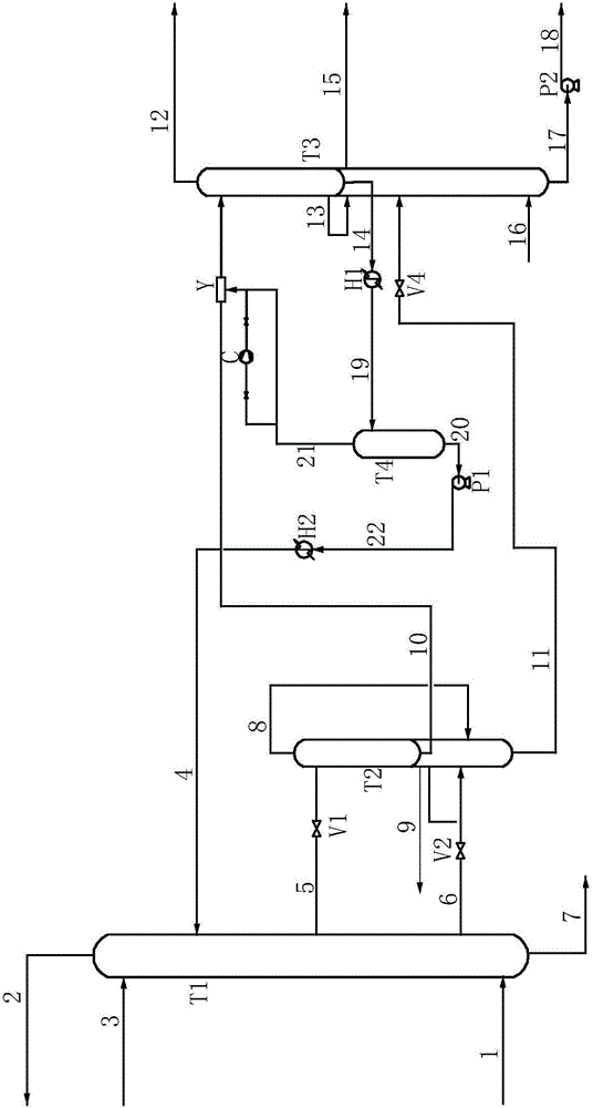
[0041] Such as figure 1 As shown, the energy-saving gas scrubbing process is described as follows:

[0042] The raw material gas enters the absorption tower T1 through the raw material gas pipeline 1, and flows in the absorption tower T1 from bottom to top; the fine cleaning methanol is introduced from the upper part of the absorption tower T1 through the fine cleaning methanol pipeline 3, and the main washing methanol is introduced from the main washing methanol pipeline 4 Imported from the upper part of the absorption tower T1, the fine-washed methanol and the main-washed methanol flow together as absorbents in the absorption tower T1 from top to bottom, and countercurrently contact with the raw material gas to wash out the acid gas in the raw material gas; the purified gas obtained is passed through Pipeline 2 is sent to the outside of the device;

[0043] The molar flow ratio of raw material gas to fine methanol is 1.5:1 to 2:1; the molar flow ratio of fine methanol to ma...

Embodiment 2

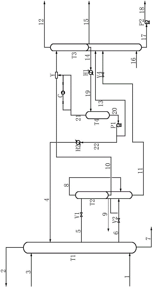
[0056] Such as figure 2 As shown, the energy-saving gas scrubbing process is described as follows:

[0057] The raw material gas enters the absorption tower T1 through the raw material gas pipeline 1, and flows in the absorption tower T1 from bottom to top; the fine cleaning methanol is introduced from the upper part of the absorption tower T1 through the fine cleaning methanol pipeline 3, and the main washing methanol is introduced from the main washing methanol pipeline 4 Imported from the upper part of the absorption tower T1, the fine-washed methanol and the main-washed methanol flow together as absorbents in the absorption tower T1 from top to bottom, and countercurrently contact with the raw material gas to wash out the acid gas in the raw material gas; the purified gas obtained is passed through Pipeline 2 is sent to the outside of the device;

[0058] The molar flow ratio of raw material gas to fine methanol is 1.5:1 to 2:1; the molar flow ratio of fine methanol to m...


PUM


Abstract

The invention relates to an energy-saving gas washing process, comprising the following steps: subjecting raw gas to countercurrent contact with methanol in an absorbing column, and washing out acidic gas from the raw gas; delivering obtained carbon-rich methanol to the upper portion of a medium-pressure flashing column, and delivering rich methanol to the lower segment of the medium-pressure flashing column; delivering via an ejector, liquid carbon-rich methanol in the medium-pressure flashing column to the upper part of a re-absorbing column, and delivering sulfur-rich methanol at the bottom of the medium-pressure flashing column to the lower part of the re-absorbing column for flashing; returning two parts of liquid flashed from the upper part of the re-absorbing column respectively to the re-absorbing column and a negative-pressure flashing column; using flashed liquid rich methanol as main washing methanol, delivering flashed gas to a suction ejector, and delivering flashed sulfur-rich methanol to a subsequent heat regeneration system.

Description

technical field [0001] The invention relates to low-temperature methanol washing, in particular to an energy-saving gas washing process. Background technique [0002] The existing low-temperature methanol washing technology generally uses low-pressure nitrogen stripping to remove CO in low-pressure sulfur-rich methanol. 2 The gas is decomposed to realize the H 2 The enrichment of S will make a lot of CO 2 The gas enters the vent tail gas, resulting in CO 2 The recovery rate is low. At the same time, when the semi-lean liquid process is adopted, carbon-rich methanol is flashed at low pressure to recover CO 2 The latter part of the liquid phase of the gas is sent to the absorption tower as the main wash methanol, and the low-pressure flash is limited by the flash temperature and flash pressure, and the CO in the main wash methanol returned to the absorption tower 2 If the content is too high, it will affect the absorption effect, resulting in an increase in the methanol c...

Claims


Application Information

Patent Timeline
Patent Type & Authority Applications(China)
IPC IPC(8): B01D53/14
CPCB01D53/1425B01D53/1475B01D53/1493
Inventor 王同宝邢涛胡有元雷雳曹孟常柳杨周华辉王姗姗
Owner SINOPEC NINGBO ENG
Why Eureka
Try Eureka