Continuous light curing three-dimensional printing equipment and use method thereof

A three-dimensional printing and light curing technology, applied in the direction of additive processing, can solve the problems of deformation, easy bending and low elastic modulus in the polymerization inhibition zone, and achieve the effect of wide selection of materials, enhanced performance, and improved performance indicators.

Active Publication Date: 2016-09-07
深圳长朗智能科技有限公司
View PDF8 Cites 33 Cited by
  • Summary
  • Abstract
  • Description
  • Claims
  • Application Information

AI Technical Summary

Problems solved by technology

[0007] A light-curing 3D printer using a semi-permeable element as a light-transmitting base plate realizes continuous light-curing molding, but the semi-permeable element also acts as a polymerization inhibitor channel, projection optical path, mechanical support structure, chemical container, etc. The role is subject to comprehensive constraints such as molecular permeability, optical transmittance, mechanical strength, surface hardness, chemical stability, etc., so it is difficult to find materials with excellent indicators for semi-permeable components, resulting in final machine performance is limited
In order to meet the requirements of permeability, fluoropolymers are commonly used as semi-permeable components at present, but the elastic modulus of this material is low, and it is easy to bend under stress during the printing process, resulting in deformation of the polymerization inhibition zone and affecting the optical path and imaging quality. This problem is especially evident in the forming process of large-format components
In addition, in order to ensure that the polymerization inhibitor can pass through the semi-permeable element smoothly, it is difficult to add a dense functional coating on the surface of the semi-permeable element for modification and reinforcement, and it is also difficult to control the temperature of the semi-permeable element by heat convection or heat conduction. control

Method used


Image

  • Continuous light curing three-dimensional printing equipment and use method thereof
  • Continuous light curing three-dimensional printing equipment and use method thereof
  • Continuous light curing three-dimensional printing equipment and use method thereof

Examples


Embodiment 1

[0057] see Figure 6 , wherein there is a thin layer of liquid photosensitive resin 604 between the light-transmitting bottom plate 602 and the molding platform 605, and the photosensitive resin includes the following components: 100 parts by weight of lauryl acrylate, 100 parts by weight of tripropylene glycol diacrylate, 3 parts by weight of camphorquinone, 2 parts by weight Parts of N, N-ethylaminobenzoate, 6 parts by weight of tetraethylthiuram disulfide. Initiating light 601 with a wavelength of 470±5 nm passes through the light-transmitting bottom plate 602 and irradiates onto the photosensitive resin thin layer 604 . Due to the light absorption effect, the light intensity of the initiation light in the resin is curve 603 . In the wavelength range of the triggering light, the absorbance of the photoinitiator camphorquinone is much higher than the absorbance of the photoinhibitor tetraethylthiuram disulfide. After light, the camphorquinone is generated by the co-initiato...

Embodiment 2

[0059] see Figure 7 , wherein there is a thin layer of liquid photosensitive resin 704 between the light-transmitting bottom plate 702 and the forming platform 705, and the composition of the photosensitive resin is the same as that of Embodiment 1. Suppressed light 701 with a wavelength of 365±5 nm passes through the light-transmitting bottom plate 702 and irradiates onto the photosensitive resin thin layer 704 . Due to the light absorption effect, the light intensity of the suppressed light in the resin is curve 703 . In the range of suppressed light wavelengths, the absorbance of the photoinhibitor tetraethylthiuram disulfide is much higher than that of the photoinitiator camphorquinone. The rate of free radical polymerization initiated by itself is very low, while camphorquinone cannot be activated, thus unable to initiate the free radical polymerization process in the system. After irradiating for 10 seconds, the light source was turned off, and it was found that the p...

Embodiment 3

[0061] see Figure 8, wherein there is a thin layer of liquid photosensitive resin 807 between the light-transmitting bottom plate 803 and the forming platform 808, and the composition of the photosensitive resin is the same as that of Embodiment 1. The inducing light 801 with a wavelength of 470±5 nm and the inhibiting light 802 with a wavelength of 365±5 nm pass through the light-transmitting bottom plate 803 and irradiate onto the photosensitive resin thin layer 807 at the same time. Due to the light absorption effect, the light intensity of the initiating light in the resin is a curve 804 , the light intensity of the inhibiting light in the resin is a curve 805 , and the difference between the intensities of the inducing light and the inhibiting light is a curve 806 . In this embodiment, the photoinitiator camphorquinone and the photoinhibitor tetraethylthiuram disulfide are activated simultaneously. In the region close to the molding platform 808, due to the initiation o...


PUM

PropertyMeasurementUnit
wavelengthaaaaaaaaaa
lengthaaaaaaaaaa
widthaaaaaaaaaa

Abstract

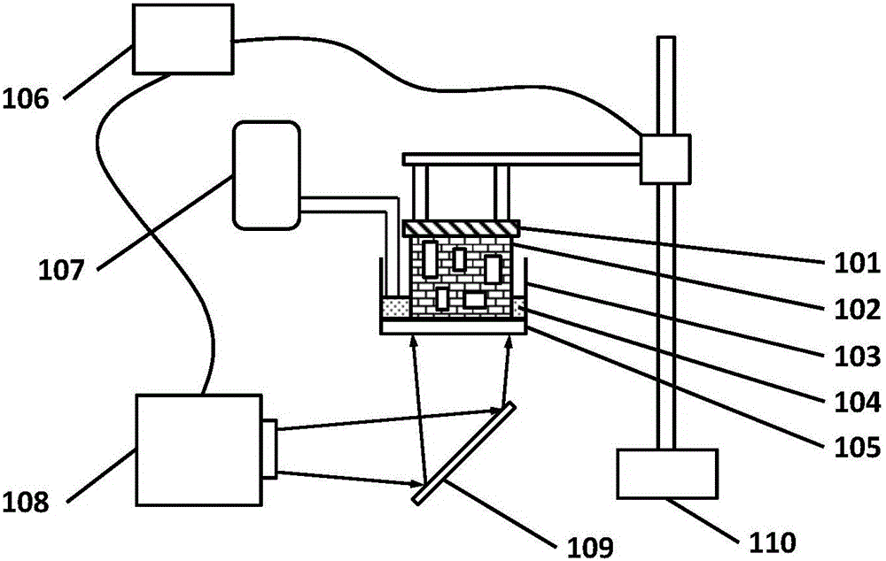
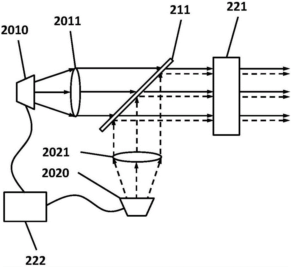
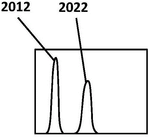
The invention provides continuous light curing three-dimensional printing equipment and a use method thereof. The continuous light curing three-dimensional printing equipment comprises a shaping platform, a resin tank, a transparent bottom plate, a feeding system, a control system and one or more projection systems, wherein each projection system comprises a light source system, a confluence light path, a digital imaging unit and a projection light path; each light source system comprises at least two independent light emitting units, emitting power of each light emitting unit can be independently controlled, and the emitting spectrums of any two light emitting units are not overlapped; the transparent bottom plate is positioned at the bottom of the resin tank, adopts a rigid flat plate structure, and the Young's modulus of used materials is more than 10GPa; the resin tank is used for loading liquid photosensitive resin including a light initiating agent and a light restraining agent, and the side wall of the resin tank is made from metal, inorganic nonmetal or high molecular materials. Through the adoption of the continuous light curing three-dimensional printing equipment and the use method thereof disclosed by the invention, the three-dimensional light curing process can be continuously performed at a high speed, and the speed and the precision are free from limit of the properties of the transparent bottom plate.

Description

technical field [0001] The invention belongs to the field of three-dimensional printing rapid prototyping, in particular to a high-speed continuous photocuring three-dimensional printing equipment. Background technique [0002] 3D printing technology is to realize the forming of 3D model by accumulating materials layer by layer through automatic numerical control. Compared with traditional processing technology, 3D printing technology does not need to make additional molds, and can directly process finished products, and can quickly obtain complex parts that are difficult to manufacture with traditional processing technologies. Therefore, 3D printing technology can shorten the product development cycle, reduce the research and development costs of enterprises, provide more effective technical solutions, and meet the growing individual needs. [0003] The stereolithography technology uses photosensitive resin as the raw material, and the computer-controlled laser scans the a...

Claims


Application Information

Patent Timeline
Patent Type & Authority Applications(China)
IPC IPC(8): B29C67/00B33Y30/00
CPCB33Y30/00
Inventor 何奕韩加军吴涛章赣阳
Owner 深圳长朗智能科技有限公司
Why Eureka
Try Eureka