
Desulfurizing tower inlet flue duct and system with desulfurized wastewater concentration function

A technology of desulfurization wastewater and inlet flue, which is applied in the direction of gaseous effluent wastewater treatment, water pollutants, water/sewage treatment, etc., can solve the problem of increasing water treatment investment, operating costs, wastewater treatment investment, high operating costs, Large flow and other issues, to achieve the effect of promoting heat transfer, simple structure, and low operating costs

Active Publication Date: 2016-09-21
山东能工低碳科技有限公司 +1
View PDF8 Cites 7 Cited by
  • Summary
  • Abstract
  • Description
  • Claims
  • Application Information

AI Technical Summary

Problems solved by technology

Due to the large flow rate and low salt concentration of this part of desulfurization wastewater, the investment and operation costs of wastewater treatment are very high.
[0005] Therefore, in the current wet desulfurization process, there are two problems in terms of water balance: 1) Although the coal-fired flue gas uses a variety of heating surfaces to extract heat from it, the temperature when it enters the desulfurization tower is still 90-150 ° C, It not only wastes heat, but also causes a large amount of water in the desulfurization slurry to be wasted in the form of evaporation; 2) The main salt content of desulfurization wastewater is very low, which not only causes water waste, but also increases water treatment investment and operating costs

Method used


Image

  • Desulfurizing tower inlet flue duct and system with desulfurized wastewater concentration function
  • Desulfurizing tower inlet flue duct and system with desulfurized wastewater concentration function
  • Desulfurizing tower inlet flue duct and system with desulfurized wastewater concentration function

Examples


Embodiment 1

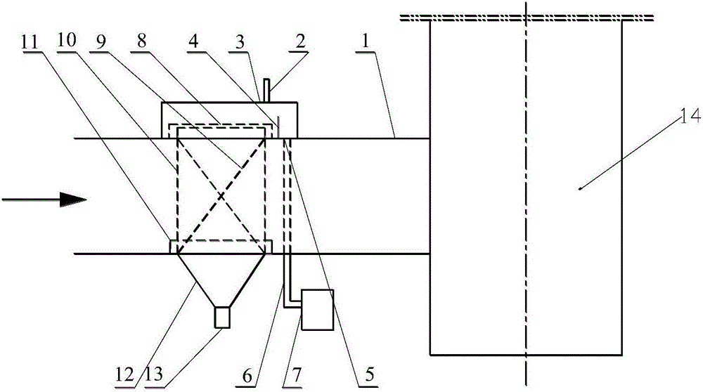
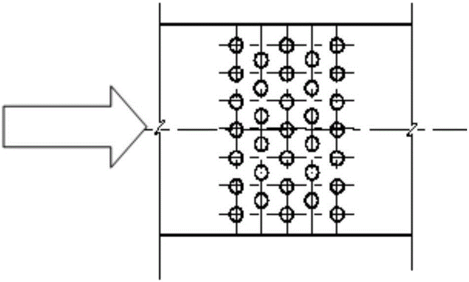
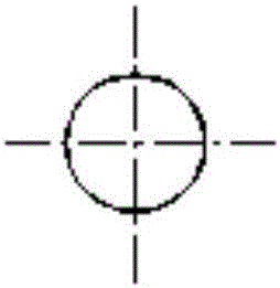
[0064] refer to figure 1 , Fig. 2(a) and Fig. 2(b), the liquid distribution element 10 is a round tube, the round tube is vertically arranged, and the round tubes are roughly parallel, the desulfurization waste water enters the water tank 3 from the water inlet 2, and the overflow weir 4 Under the action of the desulfurization wastewater, a certain water level is maintained on the upper part of the liquid distributor 8 of the water tank 3, so that a certain water pressure is maintained at the liquid distributor 8, and under the action of the water pressure, the desulfurization wastewater flows through the liquid distributor 8 to each On the top of a circular tube, the desulfurization wastewater flows continuously and from top to bottom through the outer surface of the circular tube, forming a continuous and uniform water film on the outer surface of the metal circular tube of the first liquid distribution element 10, and the flue gas flows through the circular tube. When the g...

Embodiment 2

[0067] refer to figure 1 , FIG. 3(a), FIG. 3(b) and FIG. 3(c), the liquid distribution element 10 is a groove structure, and the direction of the inner concave surface of the groove structure is opposite to the direction of the smoke flow. The liquid distribution element 10 with a groove structure is preferably a channel steel, and may also be similar in shape to a channel steel, but the material is different from the channel steel. A plurality of liquid distribution elements 10 are arranged in multiple rows, preferably 1-40 rows, and each row includes a plurality of liquid distribution elements 10 . The row spacing and column spacing between the centerlines of the liquid distribution element 10 are respectively more than twice the width of the channel steel.

[0068] The inclination direction of the liquid distribution element 10 is the same as the flow direction of the smoke, and the angle between it and the horizontal direction is preferably 45-80°.

[0069] The desulfuri...

Embodiment 3

[0071] refer to figure 1 , Fig. 4(a) and Fig. 4(b), the liquid distribution element 10 is a flat plate type, and the flat liquid distribution element is generally arranged parallel to the flow direction of the flue gas, and can be a metal plate, and the metal plate is arranged in a vertical direction. The distance between two adjacent metal plates is 100-1000mm.

[0072] The desulfurization wastewater enters the water tank 3 from the water inlet 2. Under the action of the overflow weir 4, the desulfurization wastewater maintains a certain water level on the upper part of the liquid distributor 8 of the water tank 3, so that a certain water pressure is maintained at the liquid distributor 8. Under the action of water pressure, the desulfurization wastewater flows through the liquid distributor 8 to the top of each liquid distribution element 10 shown in Figure 4, and the desulfurization wastewater flows through the liquid distribution element 10 continuously and from top to bot...


PUM


Abstract

The invention discloses a desulfurizing tower inlet flue duct with a desulfurized wastewater concentration function and a system with the desulfurized wastewater concentration function. The inlet flue duct comprises a flue duct main body, a water tank, a liquid distributor and a liquid distribution component, wherein the water tank is arranged at the upper part of the flue duct main body; the water tank is provided with a water inlet; the liquid distributor is arranged in the water tank; the liquid distribution component is arranged at the lower part of the liquid distributor; the liquid distribution component comprises a plurality of liquid distribution elements; the outer surface of each liquid distribution element is used for providing a place for forming a water film; the liquid distribution elements are vertically arranged; the upper part of each liquid distribution element penetrates through the wall of the flue duct main body, and extends into the water tank; the main body parts of the liquid distribution elements are distributed on the cross section of the flue duct main body; a wastewater collection structure is arranged below the liquid distribution elements; the lower end of the wastewater collection structure is provided with a water outlet. The inlet flue duct disclosed by the invention has the advantages that the desulfurized wastewater is formed into the water films on the outer surfaces of the liquid distribution elements, and is further concentrated by utilization of low-temperature afterheat of inlet flue gas, so that the concentration of chloride in the desulfurized wastewater reaches 40 percent, the reduction of the desulfurized wastewater is realized, and the consumption of moisture in a desulfurizing tower can be supplemented.

Description

technical field [0001] The invention belongs to the technical field of environmental pollution prevention and clean coal, and in particular relates to a desulfurization tower inlet flue and a system with the function of concentrating desulfurization wastewater. Background technique [0002] Limestone-gypsum flue gas desulfurization technology (WFGD) has become the most widely used flue gas in the world at this stage due to its advantages such as wide range of coal types, high desulfurization efficiency, high utilization rate of desulfurizers, mature technology and high operational reliability. Desulfurization process. [0003] The desulfurization process is as follows: after the boiler flue gas uses its heat through the heating surface at the tail, the flue gas with a temperature of 90-150 °C enters the desulfurization tower through the flue at the entrance of the desulfurization tower, and the desulfurization gas containing a certain amount of calcium carbonate sprayed out ...

Claims


Application Information

Patent Timeline
Patent Type & Authority Applications(China)
IPC IPC(8): B01D53/80B01D53/50C02F1/16C02F103/18C02F101/12
CPCB01D53/504B01D53/80B01D2251/404B01D2258/0283C02F1/16C02F2101/12C02F2103/18
Inventor 董勇李玉忠崔琳张立强
Owner 山东能工低碳科技有限公司
Learn More