Energy-saving industrial furnace

An industrial furnace and energy-saving technology, applied in the chemical industry, furnaces, furnace components, etc., can solve the problems of low heat utilization efficiency of industrial furnaces, achieve the effect of improving heat utilization efficiency and product quality

Active Publication Date: 2016-11-02
SHENZHEN TRIUMPH TECH ENG +1
View PDF7 Cites 8 Cited by
  • Summary
  • Abstract
  • Description
  • Claims
  • Application Information

AI Technical Summary

Problems solved by technology

[0003] Due to the influence of product production process, production organization, furnace structure, furnace base material and other factors, the heat utilization efficiency of industrial furnaces is relatively low

Method used


Image

  • Energy-saving industrial furnace
  • Energy-saving industrial furnace

Examples


Embodiment 1

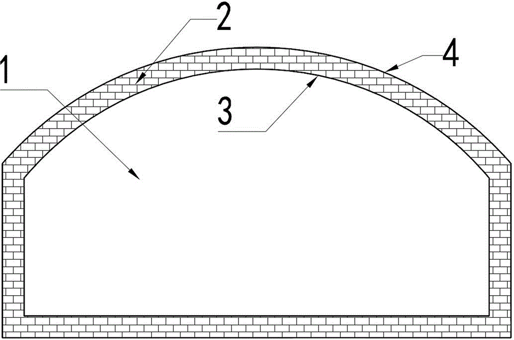
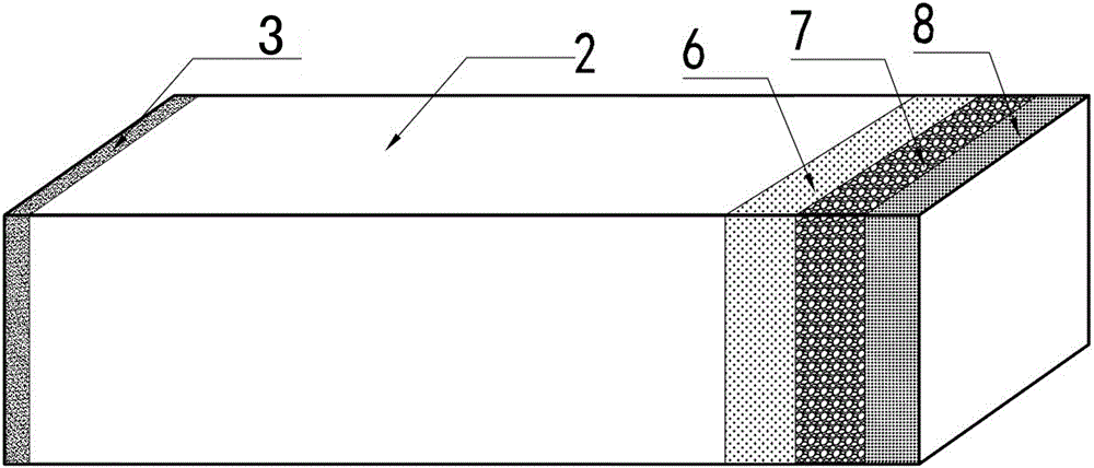
[0020] combine figure 1 and figure 2 As shown, the present invention provides a kind of energy-saving industrial furnace kiln, comprises furnace base body 2, and furnace base body 2 interior is furnace chamber 1, and furnace base body 2 adopts heat-resistant fiber, refractory brick or micronano material; The outer wall of described furnace base body 2 is coated with Covered with a combined thermal insulation coating 4, the inner wall of the furnace base 2 is coated with an infrared radiation energy-saving coating 3; the combined thermal insulation coating 4 includes an inner thermal insulation coating 6, a middle thermal insulation coating, and Layer 7 and outer thermal insulation coating 8;

[0021] The inner thermal insulation coating 6 is calculated by mass percentage, including the following components: 24% fly ash floating beads, 15% zirconia airgel, 16% kaolin, 9% bentonite, 8% sepiolite fiber, 11% zirconium Sol, 0.5% dispersant, 0.5% coalescent, 1% wetting agent, 1% ...

Embodiment 2

[0029] The basic structure of this embodiment is the same as that of Embodiment 1, the difference is:

[0030] The inner thermal insulation coating 6 includes the following components in terms of mass percentage: 17% fly ash floating beads, 19% zirconia airgel, 17% kaolin, 5% bentonite, 5% sepiolite fiber, 18% zirconium Sol, 0.5% dispersant, 2% coalescent, 0.5% wetting agent, 0.5% thickener, 0.5% defoamer and 15% deionized water;

[0031] In terms of mass percentage, the middle insulation coating 7 includes the following components: 19% hollow ceramic microspheres, 16% alumina airgel, 13% mica powder, 10% bentonite, 10% ceramic fibers, 16% aluminum sol, 0.5% dispersant, 1% coalescent, 0.5% wetting agent, 2% thickener, 1% defoamer and 11% deionized water;

[0032] The outer thermal insulation coating 8 includes the following components in terms of mass percentage: 17% hollow glass microspheres, 16% silica airgel, 18% talcum powder, 3.4% bentonite, 9% quartz fiber, 8% silica so...

Embodiment 3

[0038] The basic structure of this embodiment is the same as that of Embodiment 1, the difference is:

[0039] Inner thermal insulation coating 6 is calculated by mass percentage, including the following ingredients: 10% fly ash floating beads, 24% zirconia airgel, 23% kaolin, 5% bentonite, 6% sepiolite fiber, 20% zirconium Sol, 2% dispersant, 0.2% coalescent, 0.6% wetting agent, 0.2% thickener, 1% defoamer and 8% deionized water;

[0040] In terms of mass percentage, the middle insulation coating 7 includes the following components: 11% hollow ceramic microspheres, 14% alumina airgel, 19% mica powder, 10% bentonite, 14% ceramic fibers, 18% aluminum sol, 2% dispersant, 2% coalescent, 1% wetting agent, 0.5% thickener, 1.5% defoamer and 7% deionized water;

[0041] The outer thermal insulation coating 8 includes the following components in terms of mass percentage: 8% hollow glass microspheres, 18% silica airgel, 20% talcum powder, 8% bentonite, 3% quartz fiber, 15% silica sol,...


PUM

PropertyMeasurementUnit
thicknessaaaaaaaaaa
thicknessaaaaaaaaaa
thicknessaaaaaaaaaa

Abstract

The invention discloses an energy-saving industrial furnace. The energy-saving industrial furnace comprises a furnace base body, and the furnace base body is made of heatproof fibers, firebricks or a micro-nano material; the outer wall of the furnace base body is coated with a combined heat insulation coating layer, and the inner wall of the furnace base body is coated with an infrared radiation energy-saving coating layer; and the combined heat insulation coating layer comprises an inner heat insulation coating layer, a medium heat insulation coating layer and an outer heat insulation coating layer which are sequentially coated from inside to outside. A reinforced radiation heat transfer combined thermodynamic heat insulation energy-saving technology, which combines the infrared high-radiation technology of the high temperature-resistant infrared-energy saving coating layer with the high-efficiency heat insulation technology of the combined heat insulation coating layer, is applied, so the industrial furnace disclosed in the invention has the characteristics of effective improvement of the heat utilization efficiency, good energy saving effect, long service time, prolonged service life, and generation of the environmental protection effect.

Description

technical field [0001] The invention relates to an energy-saving industrial furnace. Background technique [0002] Industrial furnaces are high-energy-consuming equipment among many energy-consuming equipment, and their energy consumption accounts for about 10% to 70% of the energy consumption of enterprises, and some are even more. Taking the electronics industry furnace as an example, its energy consumption accounts for about 30% of the energy consumption of the electronics industry; the energy consumption of the furnaces of ceramic and glass production enterprises accounts for about 50% of the energy consumption of the enterprise, and some are even higher. [0003] Due to the influence of factors such as product production process, production organization, furnace structure, and furnace base material, the heat utilization efficiency of industrial furnaces is relatively low. For example, the thermal efficiency of the flat glass furnace is about 36%, the thermal efficiency...

Claims


Application Information

Patent Timeline
Patent Type & Authority Applications(China)
IPC IPC(8): C09D1/00C09D7/12C09D5/33C09D5/32C09D5/18F27D1/00
CPCC09D1/00C09D5/004C09D5/18C09D5/32C09D7/61C09D7/70F27D1/0033Y02P20/10
Inventor 王贵祥陈卓汤红运毕朋唐迪潘作付
Owner SHENZHEN TRIUMPH TECH ENG
Why Eureka
Try Eureka