Ultrasonic helical hole milling device and machining method

A helical milling hole and ultrasonic technology, applied in metal processing equipment, milling machine equipment, manufacturing tools, etc., can solve the problems of hole diameter error, processing defects, etc., achieve the effect of reducing cutting force, good consistency, and ensuring real-time transmission

Active Publication Date: 2016-11-09
DALIAN UNIV OF TECH
View PDF7 Cites 35 Cited by
  • Summary
  • Abstract
  • Description
  • Claims
  • Application Information

AI Technical Summary

Problems solved by technology

However, when helical milling holes are made of laminated materials, due to the different characteristics of the laminated materials, aperture errors and processing defects are prone to occur. However, there is currently no device that can integrate the functions of ultrasonic-assisted drilling and helical milling.

Method used


Image

  • Ultrasonic helical hole milling device and machining method
  • Ultrasonic helical hole milling device and machining method
  • Ultrasonic helical hole milling device and machining method

Examples


Embodiment 1

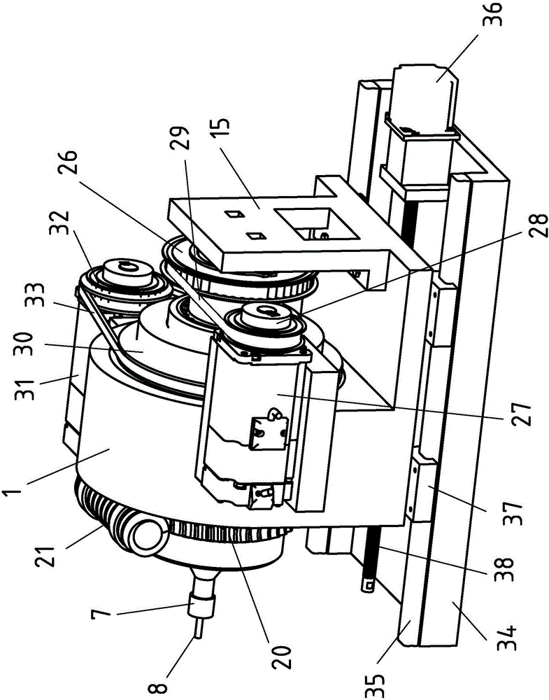
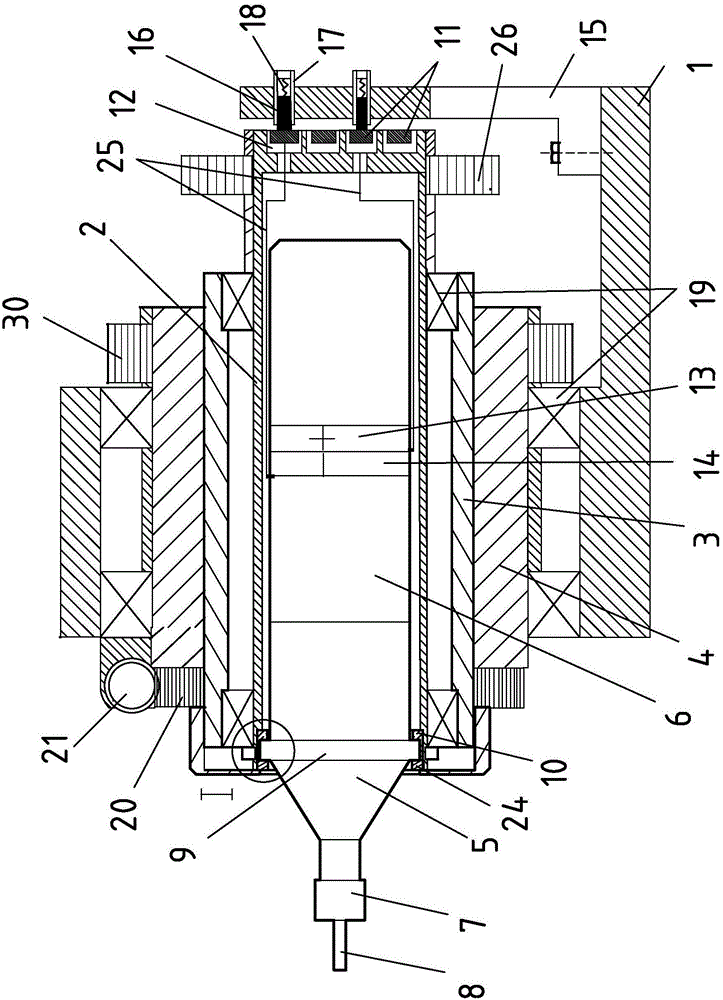
[0074] Such as Figure 1-Figure 4 As shown, an ultrasonic helical milling device includes a main shaft support 1, an ultrasonic sleeve 2, an inner eccentric sleeve 3, an outer eccentric sleeve 4, a horn 5 and a transducer located in the ultrasonic sleeve 2 6. The horn 5 is connected with the milling cutter 8 through the collet 7,

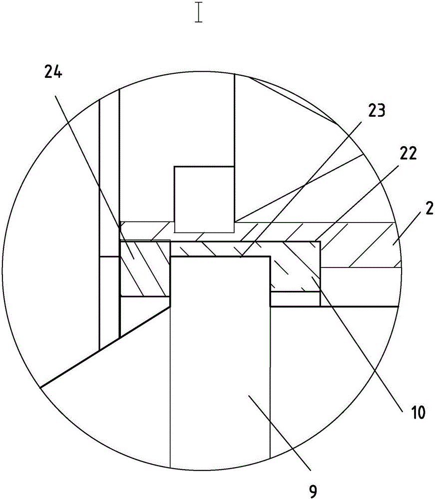
[0075] The horn 5 is connected to the transducer 6 through an annular flange 9, and the annular flange 9 is connected to the transducer 6 through an annular force sensor 10 for measuring the axial and radial force of the annular flange 9. The inner wall of the ultrasonic sleeve 2 is connected, and the bottom of the ultrasonic sleeve 2 is provided with two concentric copper rings 11, and an electrode insulating sleeve 12 is arranged between the copper ring 11 and the ultrasonic sleeve 2. Two copper rings 11 are respectively connected with positive pole 13 and negative pole 14 of described transducer 6, and described spindle support 1 is provided wit...

Embodiment 2

[0093] Such as Figure 1-Figure 6 , a kind of ultrasonic helical milling hole processing method using a kind of ultrasonic helical milling device described in embodiment 1, has the following steps:

[0094] S1. The worm 21 moves along its axial direction to realize the adjustment of the eccentricity of the axis of the horn 5, and the eccentricity of the axis of the horn 5 satisfies the following formula:

[0095] Wherein, e is the eccentricity of the axis of the horn 5, which satisfies the formula D. 1 is the diameter of the milling cutter 8, D 2 is the diameter of the hole to be processed, e 1 is the eccentricity of the inner eccentric sleeve 3, e 2 is the eccentricity of the outer eccentric sleeve 4, and α is the relative deflection angle between the inner eccentric sleeve 3 and the outer eccentric sleeve 4;

[0096] S2, turn on the ultrasonic power supply connected to the transducer 6, and adjust the resonant frequency α of the ultrasonic helical milling device;

...


PUM


Abstract

The invention discloses an ultrasonic helical hole milling device which comprises a spindle support, an ultrasonic sleeve, an inner eccentric sleeve, an outer eccentric sleeve, an amplitude-change pole and a transducer located in the ultrasonic sleeve. The amplitude-change pole is connected with a hole forming tool through a spring chuck, and the hole forming tool is a milling cutter or a grinding wheel. The amplitude-change pole is connected with the transducer through an annular flange which is connected with the inner wall of the ultrasonic sleeve through an annular force sensor used for measuring axial and radial force borne by the annular flange. The ultrasonic helical hole milling device further comprises a helical hole-milling rotation driving device connected with the ultrasonic sleeve, a helical hole-milling revolution driving device connected with the outer eccentric sleeve and a feeding system for driving the spindle support to conduct feeding along the axis of the amplitude-change pole. The invention further discloses a machining method for conducting ultrasonic helical hole milling through the ultrasonic helical hole milling device. The ultrasonic helical hole milling device and the machining method have the advantages that the hole forming quality is high, hole forming quality consistency is good, and machining stability is good.

Description

technical field [0001] The invention relates to an ultrasonic spiral milling device and a processing method, in particular to an ultrasonic-assisted spiral milling device and a hole making method, which are suitable for making holes in difficult-to-machine materials and belong to the improved technology of spiral milling. Background technique [0002] Composite materials, titanium alloys, aluminum alloys and their laminated materials, which are widely used in aerospace, national defense and military industries, are difficult to process. For example, carbon fiber composites have strong heterogeneity and various Anisotropy, high hardness, high strength, and it is not allowed to add coolant during the cutting process, resulting in poor processing quality and serious tool wear in the traditional processing process, while titanium alloy has low thermal conductivity, serious tool sticking phenomenon of aluminum alloy, and lamination Problems such as large hole defects in the mater...

Claims


Application Information

Patent Timeline
Patent Type & Authority Applications(China)
IPC IPC(8): B23C3/00B24B5/48
CPCB23C3/00B23C2220/52B24B5/48
Inventor 董志刚康仁科朱祥龙张园王毅丹杨国林
Owner DALIAN UNIV OF TECH
Why Eureka
Try Eureka