Car tail gas purifying device
An exhaust gas purification device and vehicle technology, which is applied in the direction of exhaust devices, noise reduction devices, exhaust treatment, etc., can solve problems such as poor exhaust emission, poor purification effect, and reducing agent pollution, so as to improve fuel economy and improve purification Efficiency, the effect of prolonging the contact time
- Summary
- Abstract
- Description
- Claims
- Application Information
AI Technical Summary
Problems solved by technology
Method used
Image

Examples
Embodiment 1
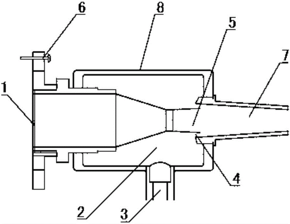
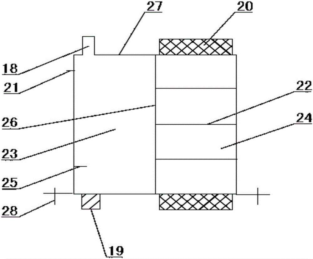
[0032] refer to Figure 1~4 , a vehicle exhaust purification device, comprising a purification injector, a purification chamber and a purification tank 27 that provides purification substances for the purification chamber. The engine exhaust pipe can be divided into three sections according to the direction in which the exhaust gas is discharged. The second section is installed in the middle of the exhaust pipe, the output end of the purifying injector is connected with the first section of the engine exhaust pipe, the output end is connected with the purification chamber, the output end of the purification chamber is connected with the third section of the engine exhaust pipe, and the purification tank 27 is connected with the exhaust pipe of the engine. The adsorption chamber 2 of the purification injector is connected to provide exhaust gas reducing agent and air for the purification chamber. The exhaust gas is sprayed into the purification chamber by the purification inject...
Embodiment 2
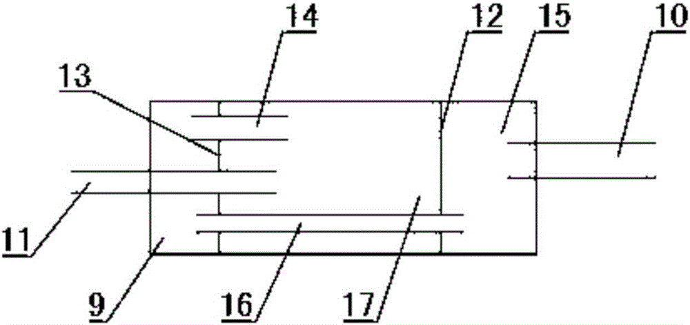
[0042] refer to Figure 5 , the clean room is divided into the first clean chamber 15, the second clean chamber 17 and the third clean chamber 9 by the first porous partition 12 and the second porous partition 13, and the outlet of the air inlet passage 10 is located at the first clean chamber In the second purification chamber 17, the entrance of the air outlet passage 11 is located in the first purification chamber 15, and the first purification chamber 15 communicates with the third purification chamber 9 through the second inner chamber passage 14, and the third purification chamber 9 communicates with the third purification chamber 9. The second purification chamber 17 communicates with the first inner cavity passage 16, and the high-temperature exhaust gas enters the second purification chamber 17 from the intake passage 10 and mixes and burns with oxygen-enriched air to form a back pressure, and then most of the NO in the exhaust gas 2 It is reduced by the reducing agen...
Embodiment 3
[0044] refer to Figure 6 , the present invention can also divide the clean chamber into the first clean chamber 15, the second clean chamber 17, the third clean chamber by the first porous partition 12, the second porous partition 13 and the third porous partition 31. Purify chamber 9 and the 4th purify chamber 29, the outlet of air inlet passage 10 is positioned at the second purify chamber 17, the entrance of air outlet passage 11 is positioned at the 3rd purify chamber 9, the 2nd purify chamber 17 and the 4th purify chamber The clean chamber 29 communicates with the first clean chamber 16, the fourth clean chamber 29 communicates with the first clean chamber 15 through the second clean chamber 14, and the first clean chamber 15 communicates with the third clean chamber 9 through the second clean chamber. The three-chamber channel 30 is connected, and the high-temperature exhaust gas enters the second purification chamber 17 from the intake channel 10 and is mixed with oxyg...
PUM
 Abstract
Description
Claims
Application Information
 - R&D
- Intellectual Property
- Life Sciences
- Materials
- Tech Scout
- Unparalleled Data Quality
- Higher Quality Content
- 60% Fewer Hallucinations
Browse by: Latest US Patents, China's latest patents, Technical Efficacy Thesaurus, Application Domain, Technology Topic, Popular Technical Reports.
© 2025 PatSnap. All rights reserved.Legal|Privacy policy|Modern Slavery Act Transparency Statement|Sitemap|About US| Contact US: help@patsnap.com