High-efficiency photo-generated negative ion purification module with scattering surface
A technology for purifying modules and scattering surfaces, used in home appliances, home heating, lighting and heating equipment, etc., can solve the problems of inability to irradiate photocatalysts, affect air circulation, and large air resistance of filters, achieve simple and intuitive application functions, improve The effect of low irradiation intensity and air resistance
- Summary
- Abstract
- Description
- Claims
- Application Information
AI Technical Summary
Problems solved by technology
Method used
Image
Examples
Embodiment 1
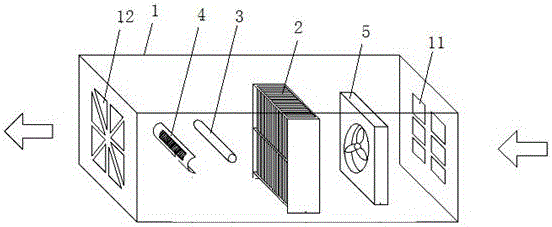
[0034] An aluminum sheet with a length of 30 cm, a width of 5.0 cm, and a thickness of 0.2 mm is used as the fin of the coated photocatalyst, and a photocatalyst coating with a thickness of about 100 μm is applied, wherein the weight percentage of the photocatalyst is 85%. Use plexiglass PMMA to make the fin bracket, use laser cutting technology to cut out slits with a width of 0.5mm, and the spacing of the slits is 0.5cm. Slits corresponding to each other are cut out on the PMMA plates at the upper and lower parts of the fin support, so that the fins coated with photocatalyst can be vertically inserted into the slits from top to bottom to be fixed. The preparation of the photocatalyst module 2 is realized through the above steps.
[0035] In the fin bracket with a height of 30cm, a width of 17cm, and a thickness of 5.0cm, there are 31 photocatalyst fins with a pitch of 0.5cm, and the total contact area between the fin photocatalyst and the air is 9300cm 2 . A UV-B ultraviol...
Embodiment 2
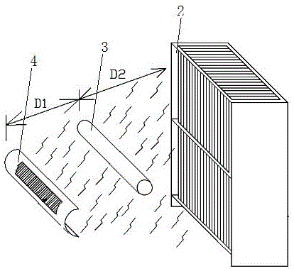
[0042] On the basis of Example 1, an aluminum foil or sheet with an aluminum purity greater than 95% and a surface roughness of 40-0.03 μm is used as the light scattering component 4 . The curvature of the scattering surface of the light scattering component 4 is 0-1.0cm -1 . Corresponding to the fin array of 30cm×17cm×5cm, the axis of the scattering surface and the axis of the ultraviolet lamp are on the same horizontal plane, they are parallel and the distance D1 is 0-15cm. The scattering surface of ultraviolet photons is oriented in all directions. In order to gather the scattered ultraviolet rays on the photocatalyst fins, the scattering surface itself has a certain size and curvature, and its relative position with the ultraviolet lamp needs to be optimized. Generally, The two are parallel to each other and keep a certain distance.
[0043] In the specific production, use the aluminum sheet that meets the above requirements as the ultraviolet scattering surface, first u...
Embodiment 3
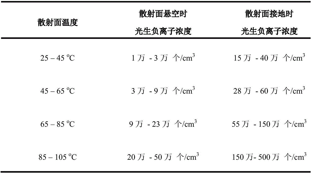
[0051] In a transparent airtight container with a volume of 1m * 1m * 1m, put into the used photocatalyst module in the embodiment one and two, wherein the fin support is 30cm high, wide and 17cm, thick and 5.0cm, the support is equipped with 31 photocatalyst fins, the weight percentage of titanium dioxide in the photocatalyst coating on the fins is 20%, the distance between adjacent fins is 0.5cm, and the total contact area between the fin photocatalyst and air is 9300 cm 2 . Two UV-B ultraviolet lamps with a power of 7W are installed horizontally at 0.5cm in front of the fin array, and each lamp is equipped with a length of 25cm, a width of 6.0cm, a thickness of 0.3mm, and a curvature of 0.01cm -1 , The scattering surface with a roughness of 20µm, the scattering surface and the central axis of the corresponding lamp tube are on the same water surface, and the distance between the two is 3.0cm, and the scattering surface is in a suspended state.
[0052] Use a needle tube t...
PUM
 Abstract
Description
Claims
Application Information
 - R&D
- Intellectual Property
- Life Sciences
- Materials
- Tech Scout
- Unparalleled Data Quality
- Higher Quality Content
- 60% Fewer Hallucinations
Browse by: Latest US Patents, China's latest patents, Technical Efficacy Thesaurus, Application Domain, Technology Topic, Popular Technical Reports.
© 2025 PatSnap. All rights reserved.Legal|Privacy policy|Modern Slavery Act Transparency Statement|Sitemap|About US| Contact US: help@patsnap.com


