Flue gas treatment device and rotary hearth furnace high-temperature and high-dust glue gas treatment system

A flue gas treatment system and flue gas treatment technology, applied in waste heat treatment, steam generation device, combustion product treatment, etc., can solve problems affecting system operation stability, large temperature range of ash melting point, and reduced service life of water cooling walls , to achieve the effect of improving waste heat utilization rate and waste heat utilization effect, improving corrosion situation and reducing heating surface

Inactive Publication Date: 2016-12-07
CHINA CITY ENVIRONMENT PROTECTION ENGINEERING LIMITED COMPANY +1
View PDF6 Cites 2 Cited by
  • Summary
  • Abstract
  • Description
  • Claims
  • Application Information

AI Technical Summary

Problems solved by technology

[0003] 1. Blockage, blockage is prone to occur in high temperature flue and low temperature flue, etc.
Because the composition and characteristics of the soot and ash of the rotary hearth furnace are complex and changeable, the temperature range of the ash melting point is large, and it is cohesive at high temperature, which is prone to blockage and affects the stability and running time of the system.
[0004] 2. Corrosion, heat exchangers such as water wall, superheater and economizer are prone to corrosion
When the rotary hearth furnace body process is used for direct reduction ironmaking, it is necessary to add a binder. Generally, the binder contains chlorine, resulting in a variety of chlorine salts in the flue gas of the rotary hearth furnace with high temperature and high dust. In the presence of water vapor "Salt mist" will be formed, which will corrode the surface of metal materials, reduce the service life of heat exchangers such as water-cooled walls, superheaters, and economizers, and affect the stability of system operation.
[0005] 3. The thermal efficiency is low. The flue gas of the rotary hearth furnace is generally recovered and utilized by conventional power plant boilers, and the heat recovery efficiency is relatively low.

Method used


Image

  • Flue gas treatment device and rotary hearth furnace high-temperature and high-dust glue gas treatment system

Examples


Embodiment 1

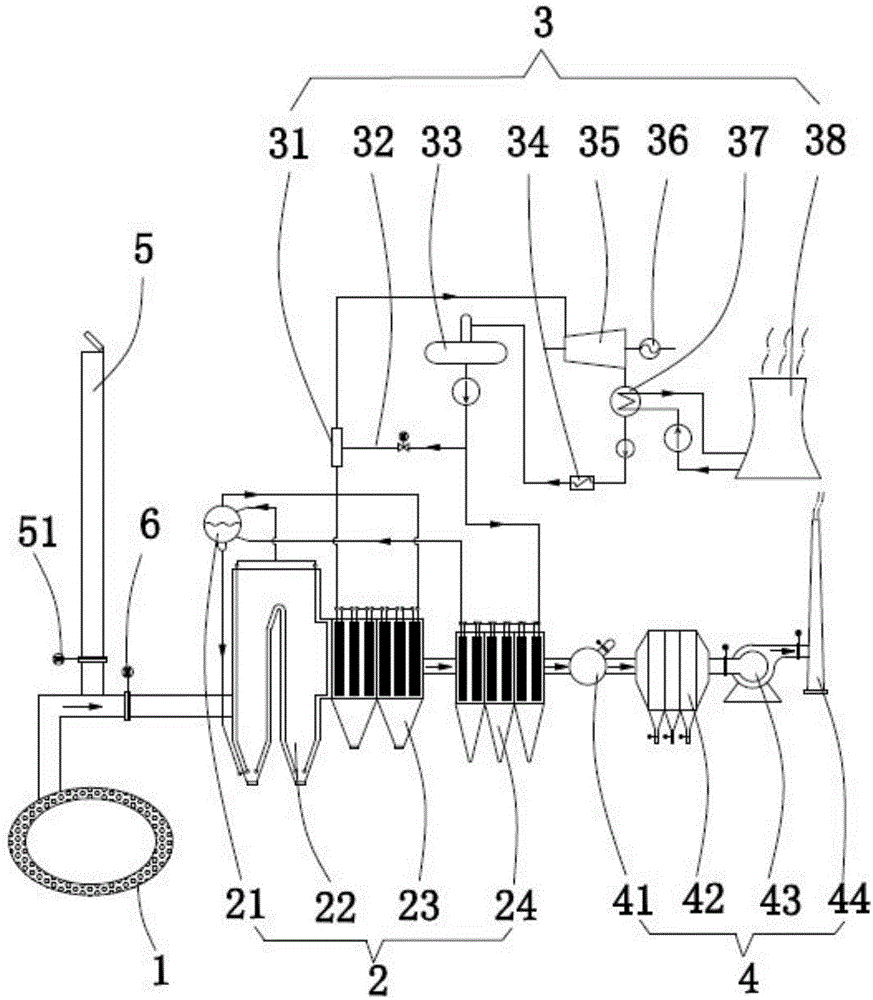
[0023] like figure 1 , the embodiment of the present invention provides a flue gas treatment device 2, which can be used to treat various flue gases produced in iron and steel plants, and is especially suitable for treating the high-temperature and high-dust flue gas produced by the rotary hearth furnace 1. The device includes a settling furnace 22, a high-temperature waste heat boiler 23, a low-temperature waste heat boiler 24, and a steam drum 21. The settling furnace 22, the high-temperature waste heat boiler 23 and the low-temperature waste heat boiler 24 are sequentially connected along the flow direction of flue gas. The flue gas inlet of 22 serves as the flue gas inlet of the flue gas treatment device 2 , and the flue gas outlet of the low-temperature waste heat boiler 24 serves as the flue gas outlet of the flue gas treatment device 2 . The settling furnace 22 is preferably in the shape of pants, and its flue gas inlet is located at the bottom of one of its trouser leg...

Embodiment 2

[0030] like figure 1 , this embodiment relates to a high-temperature and high-dust flue gas treatment system of a rotary hearth furnace, which is equipped with the flue gas treatment device 2 provided in the first embodiment above. The flue gas outlet of furnace 1 is connected. The system also includes a waste heat utilization subsystem 3, and the waste heat utilization subsystem 3 communicates with the heat exchange medium outlet of the high-temperature waste heat boiler 23 through a steam pipe.

[0031] Generally, the waste heat utilization subsystem 3 is mainly used for power generation, that is, the waste heat utilization subsystem 3 is a power generation system, and the waste heat utilization subsystem 3 includes a steam turbine 35 connected to a generator 36, and the steam turbine 35 The inlet communicates with the heat exchange medium outlet of the high-temperature waste heat boiler 23 through a steam pipe.

[0032] Further, as figure 1 , the steam outlet of the stea...

Embodiment 3

[0036] like figure 1 , this embodiment relates to a high-temperature and high-dust flue gas treatment system of a rotary hearth furnace, which is equipped with the flue gas treatment device 2 provided in the first embodiment above. The flue gas outlet of furnace 1 is connected. The system also includes a dust removal subsystem 4, and the dust removal subsystem 4 communicates with the flue gas outlet of the low-temperature waste heat boiler 24 through a low-temperature flue gas pipeline.

[0037] As one of the embodiments, the dedusting subsystem 4 includes a swirl mixer 41 and a bag filter 42 sequentially connected along the flue gas flow direction, and the swirl mixer 41 is provided with a cooling gas inlet controlled by a valve . The function of the swirling air mixer 41 is: when the working conditions that the filter bag of the bag filter 42 cannot withstand, the cooling gas (such as outdoor air) is introduced to mix with the flue gas through the opening of the valve cont...


PUM


Abstract

The invention discloses a flue gas treatment device and a rotary hearth furnace high-temperature and high-dust glue gas treatment system with the flue gas treatment device. The treatment device comprises a sedimentation furnace, a high-temperature waste heat boiler, a low-temperature waste heat boiler and a steam drum. At least part of heated walls of the sedimentation furnace are water-cooling walls. The steam drum is provided with a water inlet, a water outlet, a gas inlet and a gas outlet. The water outlet communicates with heat exchange medium inlets of all the water-cooling walls. The gas inlet communicates with heat exchange medium outlets of all the water-cooling walls. The water inlet communicates with a heat exchange medium outlet of the low-temperature waste heat boiler, and the gas outlet communicates with a heat exchange medium inlet of the high-temperature waste heat boiler. According to the flue gas treatment device, due to the fact that the heated faces in the sedimentation furnace are reduced, the waste heat utilization rate and effect of flue gas can be effectively improved, meanwhile, the phenomenon of blockage of a superheater, a body flue of a coal economizer and subsequent flues is reduced, and the corrosion situation caused by the flue gas to equipment is effectively improved.

Description

technical field [0001] The invention relates to a flue gas treatment device and a rotary hearth furnace high-temperature and high-dust flue gas treatment system equipped with the flue gas treatment device. Background technique [0002] Rotary hearth furnace is a direct reduction ironmaking process, which has been widely used in some developed countries abroad; in recent years, it has also been gradually promoted and applied in some domestic iron and steel enterprises. A large amount of high-temperature flue gas and zinc-containing dust are produced in the production process of direct reduction iron in rotary hearth furnace, which has the prospect of waste heat utilization and zinc resource recovery. However, due to the high-temperature and high-dust characteristics of the flue gas from the rotary hearth furnace, the flue gas temperature is as high as 1000°C to 1200°C, and the zinc-containing dust in the flue gas has a high viscosity at high temperatures. The following quest...

Claims


Application Information

Patent Timeline
Patent Type & Authority Applications(China)
IPC IPC(8): F22B1/18F22B33/18F22D1/00F27D17/00F23J15/04F23J1/00F23J3/00
CPCF22B1/18F22B33/18F22D1/00F23J1/00F23J3/00F23J15/04F23J2217/50F23J2700/001F27D17/004F27D2017/006Y02P10/25
Inventor 李社锋谢国海刘子豪宋自新王文坦郭华军陶玲赵波
Owner CHINA CITY ENVIRONMENT PROTECTION ENGINEERING LIMITED COMPANY
Why Eureka
Try Eureka