Hydrothermal lithium iron phosphate carbon coating method

A method of lithium iron phosphate and lithium iron phosphate technology, which is applied in the field of lithium ion battery cathode material preparation technology, can solve the problems of low product tap density electrode compaction density, uneven carbon layer, poor conductivity, etc., and achieve excellent electrical conductivity. Good chemical properties, uniform composition, and good batch stability

Active Publication Date: 2016-12-07
HEBEI UNIV OF TECH
View PDF16 Cites 1 Cited by
  • Summary
  • Abstract
  • Description
  • Claims
  • Application Information

AI Technical Summary

Problems solved by technology

[0007] The purpose of the present invention is to address the shortcomings of side reactions, uneven and loose carbon layers, low product tap density and electrode compaction density, and poor electric

Method used


Image

  • Hydrothermal lithium iron phosphate carbon coating method
  • Hydrothermal lithium iron phosphate carbon coating method
  • Hydrothermal lithium iron phosphate carbon coating method

Examples


Embodiment 1

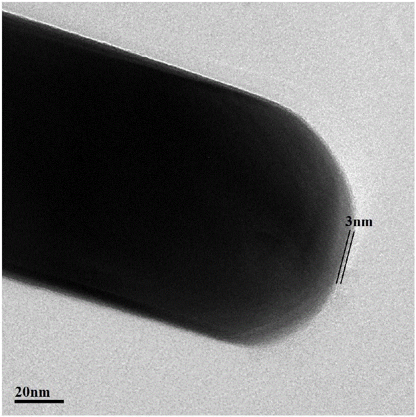
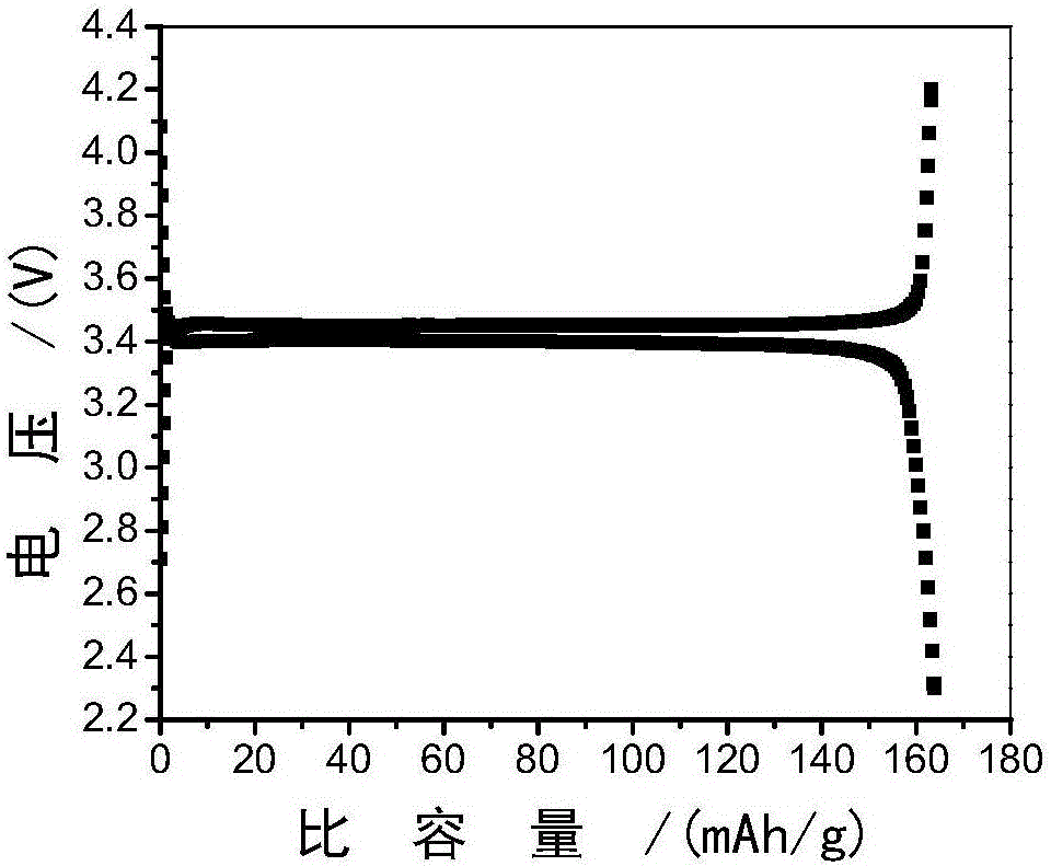
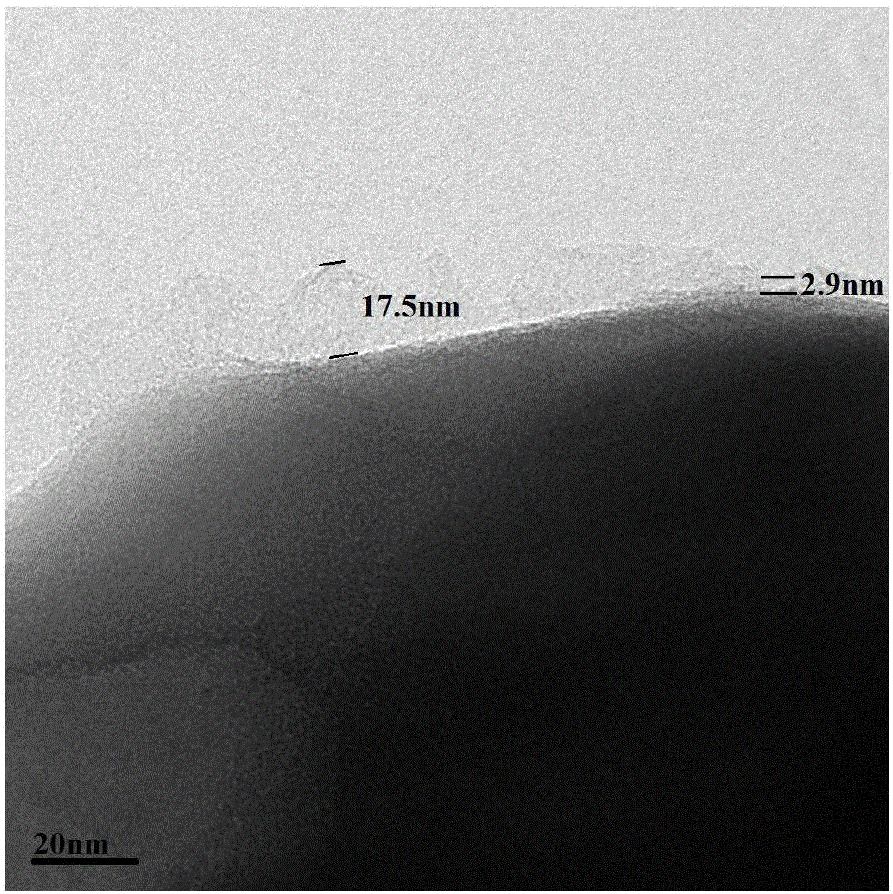
[0028] According to patent ZL201010031395.3, white powder of lithium iron phosphate is prepared. The specific steps are as follows: dissolve and dilute 555.7g of ferrous sulfate heptahydrate (2mol) to 2.0L; dilute 237.4g of 85% phosphoric acid (2.06mol) to 0.5L; dissolve 251.8g of lithium hydroxide monohydrate (6mol) Dilute to 1.5L in water. Put the phosphoric acid solution and lithium hydroxide solution into a 5L autoclave with a sealed feeding tube and a cooling coil, purge the autoclave with inert gas (nitrogen) to make all the air escape, seal the autoclave, and heat from room temperature with stirring at 200rpm When the temperature reaches 40°C, open the feed valve and exhaust valve, and add the ferrous sulfate solution prepared above with stirring at a feed rate of 300 mL / min. Seal the autoclave, stir for 20 minutes, open the feed valve and exhaust valve, and then add the prepared lithium hydroxide solution as a pH adjuster. The solution is prepared by dissolving 8g of l...

Embodiment 2

[0031] Example 2 (Compared with Example 1, the degree of oxidation is different)

[0032] Put the lithium iron phosphate powder in Example 1 in an electric heating blast drying box, keep it at 180℃ for 1h, take it out, and measure Fe 3+ The content is 2.0%. The other steps are the same as in Example 1. The electrochemical performance, carbon content and ferric iron content of the product are shown in Table 1.

Embodiment 3

[0037] Example 3 (Olefin ratio 1:7)

[0038] The oxidized lithium iron phosphate powder in Example 1 was placed in a tube furnace, and high-purity argon was first introduced. In a high-purity argon atmosphere, the heating rate was controlled to 4°C / min and heated from room temperature to 570°C. , And keep it for 2h, continue to increase the temperature in the furnace to 630℃ at a heating rate of 4℃ / min, then change to a reaction gas with a volume ratio of 2-butene to argon of 1:7, and control the gas flow to 50mL / min , 4h later, switch the gas to high-purity argon again, and cool to below 100℃ to obtain LiFePO 4 / C Composite materials. The electrochemical performance, carbon content and ferric iron content of the product are shown in Table 1.


PUM

PropertyMeasurementUnit
Compaction densityaaaaaaaaaa

Abstract

The invention discloses a hydrothermal lithium iron phosphate carbon coating method which includes the steps: first, placing lithium iron phosphate prepared by a hydrothermal method in air atmosphere and heating and drying the lithium iron phosphate for 1-3 hours; second, placing the dried lithium iron phosphate in a high-temperature furnace, keeping the temperature of 570-600 DEG C for 1-2 hours in protective gas atmosphere, leading reaction gas at the temperature of 600-650 DEG C, performing reaction for 4-6 hours, switching the reaction gas into protective gas and cooling the lithium iron phosphate to below 100 DEG C to obtain a LiFePO4/C composite material. The reaction gas is prepared by mixing olefin gas with the protective gas. A carbon coating layer with uniform components, controllable thickness and good conductivity can be obtained under the catalytic action of Fe3+ on the surface of LiFePO4 for olefin carbonization. The material has excellent electrochemical performance, and tap density can be improved.

Description

Technical field [0001] The present invention belongs to the technical field of lithium ion battery positive electrode material preparation technology. Specifically, the present invention relates to a hydrothermal method for carbon coating of lithium iron phosphate. technical background [0002] With the ever-increasing energy crisis, the search for renewable energy has become the focus of competition among countries in the world. The currently discovered renewable energy sources such as solar energy, tidal energy, wind energy, etc. have regional and temporal barriers, so to make full use of these energy sources, smart grids or large-scale energy storage systems are required. Lithium-ion batteries are favored because of their high voltage, large specific energy, safety, and environmental protection. Among them, as the third-generation cathode material of lithium-ion batteries, lithium iron phosphate (LiFePO 4 ), which has the advantages of abundant raw materials, low price, safet...

Claims


Application Information

Patent Timeline
IPC IPC(8): H01M10/0525H01M4/58H01M4/583H01M4/139
CPCH01M4/139H01M4/366H01M4/5825H01M4/583H01M10/0525Y02E60/10
Inventor 欧秀芹闵长青时志翔梁广川王丽
Owner HEBEI UNIV OF TECH
Why Eureka
Try Eureka