
Optical fiber vibration identification system based on phi-OTDR technology and optical fiber vibration identification method thereof

An optical fiber vibration and identification system technology, applied in measuring devices, instruments, measuring ultrasonic/sonic/infrasonic waves, etc., can solve the problems of being susceptible to interference and low identification reliability, and improve the monitoring range, signal-to-noise ratio, and sensitivity. high effect

Active Publication Date: 2016-12-14
ZHEJIANG UNIV
View PDF2 Cites 40 Cited by
  • Summary
  • Abstract
  • Description
  • Claims
  • Application Information

AI Technical Summary

Problems solved by technology

The existing optical fiber signal classification methods still mainly use a single type of characteristic parameter as the basis for identification, which is simple and easy to be interfered, and the identification reliability in complex environments is low. Therefore, how to extract signal features to achieve vibration behavior The distinction between signals and environmental interference signals and the distinction between different types of vibration behavior signals have become the key to restricting its role in practical applications and directly determine the application prospects of the system

Method used


Image

  • Optical fiber vibration identification system based on phi-OTDR technology and optical fiber vibration identification method thereof
  • Optical fiber vibration identification system based on phi-OTDR technology and optical fiber vibration identification method thereof
  • Optical fiber vibration identification system based on phi-OTDR technology and optical fiber vibration identification method thereof

Examples


Embodiment Construction

[0042] The present invention is described in further detail with reference to the accompanying drawings and specific embodiments.

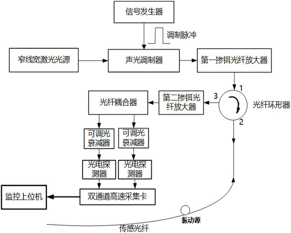
[0043] In the embodiment of the present invention, the hardware structure of the system includes: a narrow linewidth fiber laser, an acousto-optic modulator, a signal generator, a first erbium-doped fiber amplifier, a fiber circulator, a sensing fiber, a second erbium-doped fiber amplifier, an optical fiber Coupler, first adjustable optical attenuator, second adjustable optical attenuator, first photodetector, second photodetector, dual-channel high-speed data acquisition card, monitoring host computer. The hardware structure diagram of the system is as follows figure 1 shown.

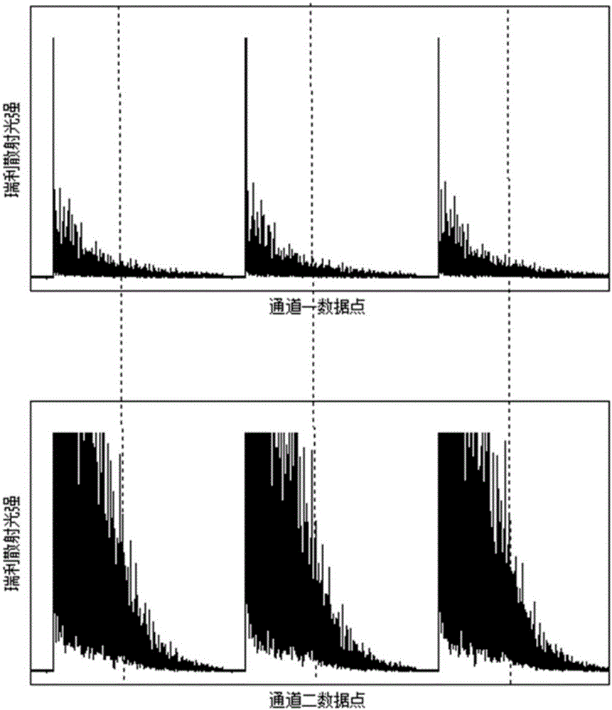
[0044] The working wavelength of the narrow linewidth laser is 1550nm, and the linewidth is less than 100kHz, which is used to emit strong coherent continuous probe light; The strong coherent continuous detection light emitted by the wide laser is modulated into pulsed l...


PUM

PropertyMeasurementUnit
Snraaaaaaaaaa

Abstract

The invention provides an optical fiber vibration identification system based on a phi-OTDR technology and an optical fiber vibration identification method thereof. The monitoring distance of the system is greatly enhanced through a dual-path detection structure; the adaptability of the system for environmental noise changes is enhanced by the method of characteristic threshold dynamic updating, and a vibration event is accurately positioned; background noise in signals can be greatly reduced through spectral subtraction noise reduction under the condition of maintaining the signal characteristic and energy of the vibration signals, and the signal-to-noise ratio of the signals and the sensitivity of system detection can be enhanced; and multi-characteristic parameter mode identification is performed on the vibration signals from the time domain and the wavelet domain so that the influence of other complex time-dependent interference noise can be effectively avoided, the correct rate of vibration event detection and vibration type classification can be enhanced, the false alarm rate of the system can be reduced, the detection performance of a vibration detection system based on the OTDR technology in the actual complex noise environment can be enhanced, and the national major project application requirements in the aspects of boundary safety and long-distance pipeline safety can be met.

Description

technical field [0001] The invention relates to the technical field of optical fiber sensors, in particular to an optical fiber vibration identification system and method based on Φ-OTDR technology. Background technique [0002] Distributed optical fiber sensing system has very obvious technical advantages in sensor network applications: small size, light weight, very good reliability and stability; passive system, energy-dependent, can greatly save power supply equipment and lines Low cost, suitable for long-distance use; anti-electromagnetic interference, anti-corrosion, completely unaffected by lightning, can work in harsh chemical environments, field environments and places with strong electromagnetic interference; no radiation, no flammable and explosive materials, waterproof , Environmental protection, etc. Therefore, there is an urgent need for long-distance, intelligent optical fiber sensing systems in security, military, pipeline transportation and other fields. ...

Claims


Application Information

Patent Timeline
IPC IPC(8): G01H9/00
CPCG01H9/004
Inventor 徐铖晋叶炜
Owner ZHEJIANG UNIV
Learn More