
Device for collecting vapor in flue gas

A water vapor and flue gas technology, applied in the field of heat exchange, can solve the problems of complicated installation, high cost, and insufficient water vapor collection effect, and achieve the effects of reliable operation, low equipment cost and better cooling effect.

Inactive Publication Date: 2017-01-04
SHANGHAI UNIVERSITY OF ELECTRIC POWER
View PDF8 Cites 2 Cited by
  • Summary
  • Abstract
  • Description
  • Claims
  • Application Information

AI Technical Summary

Problems solved by technology

[0003] Chinese patent CN 202361629U discloses a high-efficiency flue gas condensation waste heat recovery device, which includes sequentially connected boiler exhaust pipes, static pressure box type flue gas condensed water collection box, high-efficiency flue gas-water heat exchanger, flue gas collection box, Flue gas discharge pipe, cooling water inlet pipe, cooling water outlet pipe, this utility model turns the water vapor in the boiler flue gas into condensed water, recovers the latent heat and sensible heat contained in the flue gas, and the condensation generated after the flue gas is cooled The water is discharged, but because the device is arranged vertically as a whole, it needs an independent support and hanger, which is more complicated to install and the cost is higher; the device has only one stage of water vapor collection process, and the heat exchange effect is more obvious, but the water vapor collection effect Not very thorough, there is still a large amount of water vapor in the boiler exhaust, and the problem of a large amount of water vapor discharge has not been effectively solved

Method used


Image

  • Device for collecting vapor in flue gas

Examples


Embodiment 1

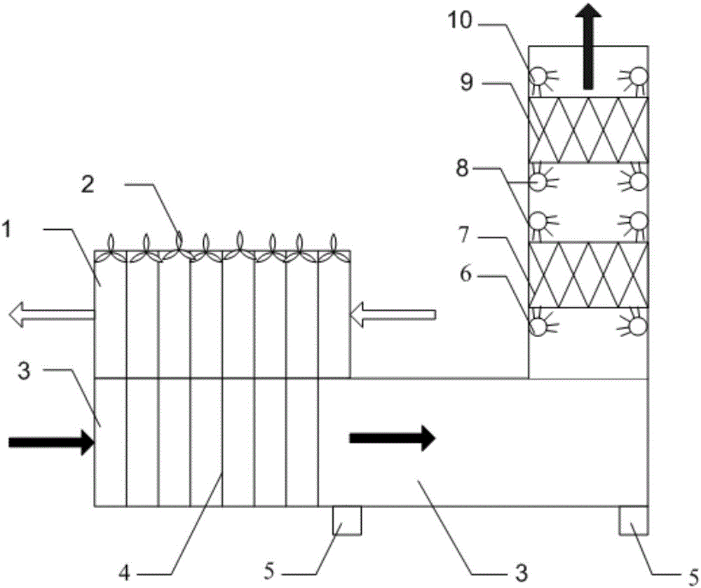
[0026] A device for collecting water vapor in flue gas, such as figure 1 As shown, it includes a heat exchange unit 4 and a water vapor collection unit. The upper part of the heat exchange unit 4 is provided with an air passage 1, and the lower part is provided with a flue gas passage 3. The heat exchange unit 4 is connected to the water vapor collection unit through the flue gas passage 3. There are multiple drainage pipes 5 at the bottom of the flue gas passage 3, and the water vapor collection unit is provided with a first-level cold water nozzle 6, a first-level water vapor collector 7, a second-level cold water nozzle 8, and a second-level water vapor collector 9 from bottom to top. And three-stage cold water nozzle 10. The heat exchange unit 4 adopts a heat exchange tube group, and the heat pipe used is a gravity heat pipe or a gravity-assisted heat pipe. The heat exchange tube group uses a low boiling point substance as a heat exchange medium. The low boiling point subs...


PUM


Abstract

The invention relates to a device for collecting vapor in flue gas. The device comprises a heat exchange unit and a vapor collecting unit, an air channel is arranged on the upper portion of the heat exchange unit, a flue gas channel is arranged on the lower portion of the heat exchange unit, the heat exchange unit is connected with the vapor collecting unit through the flue gas channel, the bottom of the flue gas channel is provided with a plurality of drain pipes, and the vapor collecting unit comprises a plurality of cold water sprayers and a vapor collector. Air exchanges heat with the flue gas through the heat exchange unit, part of the vapor in the flue gas is condensed, the flue gas flows to the vapor collecting unit and is further cooled, the vapor in the flue gas is further collected, and the low-temperature flue gas is discharged. Compared with the prior art, the device is simple, low in cost, capable of continuously running, good in flue gas recovery effect and high in universality, running cost can be greatly reduced, economical efficiency is improved, the emission problem of the vapor is effectively solved, and environmental protection level can be improved.

Description

technical field [0001] The invention belongs to the technical field of heat exchange, in particular to a device for collecting water vapor in flue gas. Background technique [0002] In order to improve system efficiency and meet environmental protection requirements, most modern thermal power generating units are equipped with desulfurization devices. In order to reduce the emission of water vapor, a flue gas heat exchanger (GGH) needs to be installed, but the operation of the GGH will cause blockage problems. Many power plants have removed the GGH due to this problem. After the removal, the water vapor in the boiler exhaust gas has increased greatly. A large amount of water vapor came out of the chimney and fell around the power station, affecting the environment. Especially for the iron and steel industry, after molten iron is melted, it will be cooled by spraying water, causing a large amount of water vapor to emerge. In order to solve the problem of water vapor emissio...

Claims


Application Information

Patent Timeline
Patent Type & Authority Applications(China)
IPC IPC(8): F22B37/26F28D15/02F23J15/06
CPCF22B37/26F23J15/06F28D15/02Y02E20/30
Inventor 李彦朱群志姜未汀张涛段芮余杨敏
Owner SHANGHAI UNIVERSITY OF ELECTRIC POWER
Learn More