Deep denitration combustion method for tangential boiler
A combustion method and boiler technology, applied in the direction of combustion method, use of multiple fuels, combustion types, etc., can solve problems such as limited scope of application, ammonia escape, high requirements for boiler working conditions, etc., achieve wide applicability, reduce nitrogen Oxygen emission value, effect of reducing denitrification cost
- Summary
- Abstract
- Description
- Claims
- Application Information
AI Technical Summary
Problems solved by technology
Method used
Image
Examples
Embodiment 1
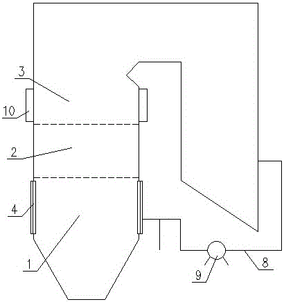
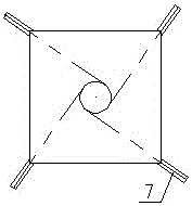
[0035] Such as figure 1 , figure 2 , image 3 As shown, the furnace of the tangential boiler is divided from bottom to top into the main combustion zone 1, the reduction zone 2 and the burnout zone 3. The four burners 4 are arranged in four corners, and each burner 4 is provided with several cross-arranged longitudinally The primary air nozzles 5 and the secondary air nozzles 6 are provided with a layer of reduction inhibitor nozzles 7 at the four corners of the furnace wall between the primary air nozzles 5 and the secondary air nozzles 6. The reduction inhibitor nozzles 7 at the four corners form a tangential circle. The tail flue behind the boiler air preheater is connected to all reduction inhibitor nozzles 7 through pipeline 8 and fan 9; the burn-out wind box 10 in the burn-out zone is provided with four-layer burn-out air nozzles 11; The tangential boiler deep denitrification combustion method is to send coal to the main combustion zone 1 of the furnace through the primar...
Embodiment 2
[0038] Such as Figure 4 As shown, the difference between this embodiment and the first embodiment is that the four-corner reduction inhibitor nozzles 7 are arranged in the primary air nozzles 5 or the secondary air nozzles 6 of each burner, and the reduction inhibitor nozzles 7 have a smaller caliber than The diameter of the primary air nozzle 5 or the diameter of the secondary air nozzle 6; the amino reduction inhibitor is sprayed from the reduction inhibitor nozzle 7 provided in the primary air nozzle 5 or the secondary air nozzle 6 in a manner of forming an imaginary tangent circle In; Since the caliber of the reduction inhibitor nozzle 7 is smaller than the caliber of the primary air nozzle 5 or the caliber of the secondary air nozzle 6, it does not affect the original primary air or secondary air injected into the furnace, which can achieve the same as the first embodiment Technical effect
Embodiment 3
[0040] Such as Figure 5 , Image 6 As shown, the difference between this embodiment and the first embodiment is only: the reduction inhibitor nozzle 7 is set on the four furnace walls of the reduction zone 2 between the main combustion zone 1 and the burnout zone 3; each furnace wall is provided with Two reduction inhibitor nozzles 7; the amino reduction inhibitor is sprayed from the two reduction inhibitor nozzles 7 on each furnace wall into the furnace in an imaginary tangent circle; the diameter of the reduction inhibitor nozzle 7 is 1-10mm , The opening is fan-shaped, the opening angle is between 10°~150°, the injection speed of the amino reduction inhibitor is between 10m / s~400m / s, the deflection angle of the reduction inhibitor nozzle 7 can be adjusted to adjust the diameter of the circle And the direction of rotation to meet the needs of different working conditions, and can achieve basically the same technical effect as the first embodiment;
PUM
 Abstract
Description
Claims
Application Information
 - R&D
- Intellectual Property
- Life Sciences
- Materials
- Tech Scout
- Unparalleled Data Quality
- Higher Quality Content
- 60% Fewer Hallucinations
Browse by: Latest US Patents, China's latest patents, Technical Efficacy Thesaurus, Application Domain, Technology Topic, Popular Technical Reports.
© 2025 PatSnap. All rights reserved.Legal|Privacy policy|Modern Slavery Act Transparency Statement|Sitemap|About US| Contact US: help@patsnap.com


