
Ice breaking and removing method based on plasma impact jet flow

A plasma and impinging jet technology, applied in deicing devices, aircraft parts, transportation and packaging, etc., can solve the problems of changing the aerodynamic shape of the aircraft, insufficient deicing speed, and structural fatigue, so as to avoid structural fatigue problems and reduce air pollution. Breakdown voltage, the effect of easy electrical parameter control

Inactive Publication Date: 2017-01-11
NAT UNIV OF DEFENSE TECH
View PDF6 Cites 19 Cited by
  • Summary
  • Abstract
  • Description
  • Claims
  • Application Information

AI Technical Summary

Problems solved by technology

However, traditional mechanical deicing methods will change the aerodynamic shape, and skin vibration will cause structural fatigue
[0004] The traditional hot air jet requires a pipeline supply system, the heat utilization rate is low and the bleed air pipeline will increase the weight of the aircraft, and the application range of the electric heating anti-icing is limited and the power consumption is large
[0005] In addition, in the exploration of deicing technology, some people proposed to use dielectric barrier discharge plasma actuator for deicing. The main deicing principle of this method is the Joule heating effect of gas discharge, and the dielectric barrier discharge plasma actuator used is insulating glue. It is pasted on the surface of the aircraft skin that is prone to freezing, and half of the positive and negative electrodes are exposed to the air. There are problems such as changing the aerodynamic shape of the aircraft, the electrodes are directly in contact with the air, and the heat generation of the plasma actuator is limited. When the aircraft is flying under severe weather conditions, the icing intensity is high, the icing speed is fast, and the aerodynamic hazard is great. The deicing speed of the dielectric barrier discharge plasma actuator is relatively insufficient
[0006] Thereby urgently need a kind of faster and more efficient deicing method, avoid the aircraft out of control stall caused by icing

Method used


Image

  • Ice breaking and removing method based on plasma impact jet flow
  • Ice breaking and removing method based on plasma impact jet flow
  • Ice breaking and removing method based on plasma impact jet flow

Examples


Embodiment Construction

[0033] In order to make the objectives, technical solutions and advantages of the present invention clearer, the embodiments of the present invention will be described in further detail below in conjunction with the accompanying drawings.

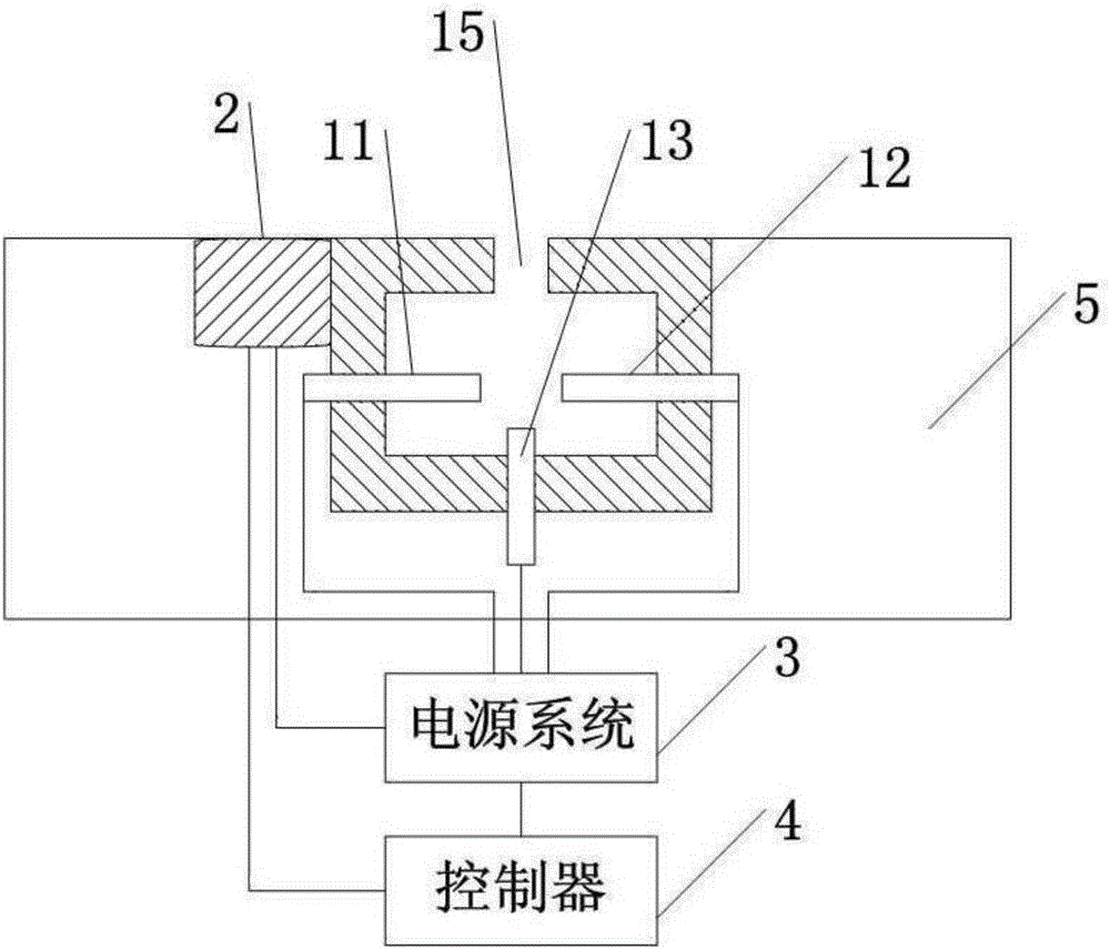
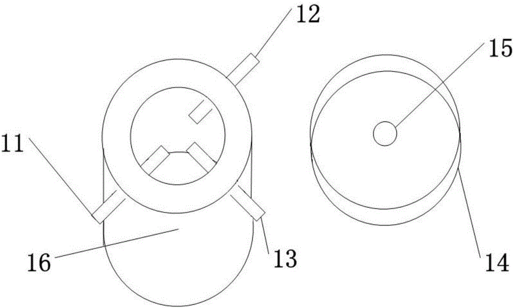
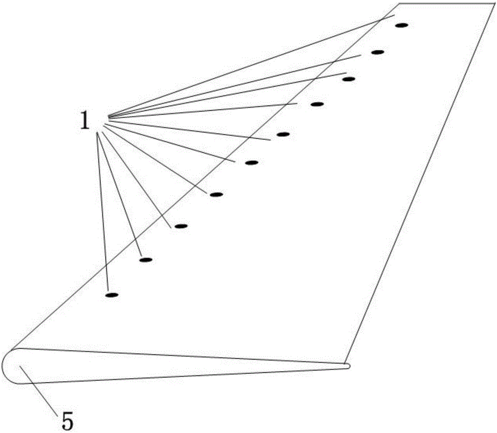
[0034] In this embodiment, the wing on the aircraft is selected as the application object for ice breaking, such as figure 1 As shown, the plasma exciter 1 and the icing detector 2 are both installed on the wing 5. The wing 5 is provided with mounting holes for installing the plasma exciter 1 and the icing detector 2. The plasma exciter 1 and the icing detector 2 are installed in the corresponding mounting holes on the wing 5. After the plasma exciter 1 and the icing detector 2 are installed, the outer surface of the plasma exciter 1 and the icing detector 2 are the same as the aircraft on the wing. The surface of the wing is flush, that is, neither convex nor concave, so that the aerodynamic shape of the wing installed with the plasma impinge...


PUM


Abstract

The invention discloses an ice breaking and removing method based on plasma impact jet flow. In an easily-icing zone of an object with the ice removing demand, a plasma actuator and an icing detector are installed in the mode of being flush with the object plane of the easily-icing zone, wherein the plasma actuator and the icing detector are connected with a controller; when the icing detector detects that the object plane of the easily-icing zone ices, the controller controls the plasma actuator located in the easily-icing zone to work and controls the discharging power and frequency and the working time of the plasma actuator, and periodic high-temperature and high-dynamic-pressure jet flow generated by the plasma actuator is used for impacting an ice layer to make the ice layer rapidly vibrate, deform and break and even directly crushing and thawing the ice layer to achieve ice breaking. The plasma ice removing technology makes electric parameter control, light-and-small design and distributed layout easy, has the advantages of rapidness, high efficiency and low energy consumption and can be widely applied to ice breaking and removing for various air vehicles or other objects with the ice removing demand.

Description

Technical field [0001] The invention belongs to the technical field of surface deicing technology and plasma physics application technology, and relates to a deicing method based on plasma impingement jets, which is used to quickly break the surface ice of various aircraft or other objects with deicing requirements. Background technique [0002] Icing is common in engineering practice and applications, such as power transmission lines in severe cold environments. In low temperature rain and snow, the environment has high humidity, and a large amount of water vapor condenses on the surface of the wires to cause icing. When icing, both sides of the pole / tower If the tension is unbalanced, there will be failures such as inverted poles / towers, and the power system will be terminated. There are also various types of aircraft that are prone to icing during flight. When the aircraft is flying in icy weather conditions below the freezing point, the supercooled water droplets in the atmos...

Claims


Application Information

Patent Timeline
IPC IPC(8): B64D15/00
CPCB64D15/00
Inventor 罗振兵王林蒋浩夏智勋周岩
Owner NAT UNIV OF DEFENSE TECH
Learn More