Thermal power generation system based on boiler tail bypass flue

A bypass flue, thermal power generation technology, used in steam generation, machines/engines, lighting and heating equipment, etc., can solve problems such as low temperature corrosion, increase the efficiency of power generation systems, affect steam condensation and heat release, and avoid serious corrosion. problems, reducing volume and cost, and good engineering feasibility

Inactive Publication Date: 2017-01-11
UNIV OF SHANGHAI FOR SCI & TECH
View PDF6 Cites 4 Cited by
  • Summary
  • Abstract
  • Description
  • Claims
  • Application Information

AI Technical Summary

Problems solved by technology

The outstanding problems of this air preheating scheme are: the heat exchange temperature difference between the flue gas and the air in the first stage air preheater is very small, resulting in a large equipment volume and investment cost of the low temperature air preheater; After the low-temperature flue gas preheating air, the air temperature rise that can be obtained is small, so that the amount of flue gas that can enter the bypass flue for exhaustion and extraction is small, so the coal-saving benefits of the unit are relatively limited; moreover, the more prominent problem Yes, because the temperature of the tube wall on the heating surface is very low, the heating surface of the low-temperature air preheater inevitably faces severe low-temperature corrosion. Therefore, the heating surface of the low-temperature air preheater must be made of very expensive corrosion-resistant materials, which seriously reduces The engineering feasibility and investment economy of the bypass flue scheme
[0005] In addition, even if the boiler supply air is preheated by using steam extraction from the steam turbine, the efficiency of the power generation system will increase to a certain extent. Therefore, air will leak into the steam side and affect the ability of steam to condense and release heat. Therefore, it is necessary to configure an extractor device in the heater. The investment and operation and maintenance costs of the fan device are relatively large

Method used


Image

  • Thermal power generation system based on boiler tail bypass flue
  • Thermal power generation system based on boiler tail bypass flue
  • Thermal power generation system based on boiler tail bypass flue

Examples


Embodiment 1

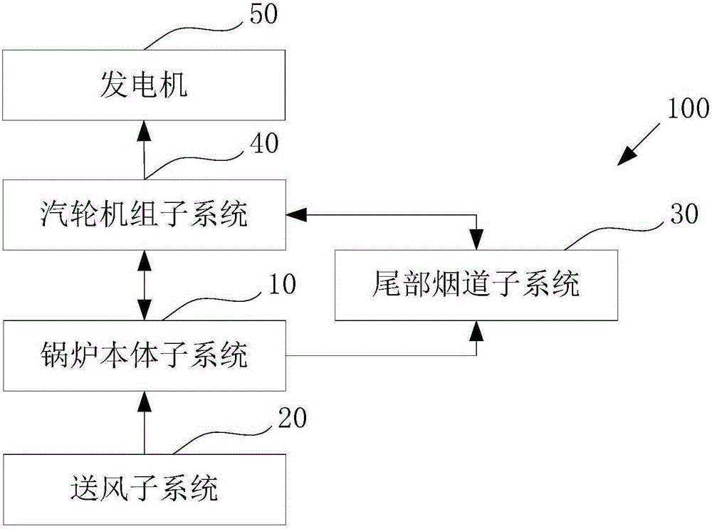
[0022] figure 1 It is a structural block diagram of a thermal power generation system based on a boiler tail bypass flue in Embodiment 1 of the present invention.

[0023] Such as figure 1 As shown, the thermal power generation system 100 based on the bypass flue at the boiler tail uses the heat generated by fuel combustion to generate electricity, which can not only reduce high-pressure steam extraction to improve power generation efficiency, but also avoid the heat exchange caused by low-temperature flue gas preheating air. Corrosion of thermal equipment, thermal power generation system 100 based on boiler tail bypass flue includes: boiler body subsystem 10 , air supply subsystem 20 , tail flue subsystem 30 , steam turbine unit subsystem 40 and generator 50 .

[0024] The heat generated by the combustion of fuel in the boiler sub-system 10 heats the feed water of the turbine sub-system 40 to form high-temperature and high-pressure steam, which then enters the turbine sub-sy...

Embodiment 2

[0053] The following is the description of the second embodiment.

[0054] In the second embodiment, the same symbols are assigned to the same structures as those in the first embodiment, and the same descriptions are omitted.

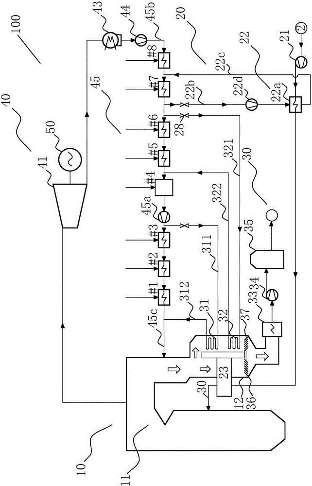
[0055] Figure 4 It is a structural schematic diagram of a thermal power generation system based on a boiler tail bypass flue in Embodiment 2 of the present invention.

[0056] Such as Figure 4As shown, in the second embodiment, the thermal power generation system 200 based on the boiler tail bypass flue includes: the boiler body subsystem 10, the air supply subsystem 220, the tail flue subsystem 30, the steam turbine unit subsystem 40 and the generator 50.

[0057] The air supply subsystem 220 includes: a blower fan 21 , a front air preheater 222 and a flue air preheater 23 . The pre-air preheater 222 uses the high-temperature condensed water at the outlet of the fourth low-pressure heater #5 to preheat the ambient cold air. The pre-air pre-heate...


PUM


Abstract

The invention provides a thermal power generation system based on a boiler tail bypass flue. The thermal power generation system comprises a boiler body subsystem, an air supply subsystem, a tail flue subsystem, a turboset subsystem and an electric generator, wherein the boiler body subsystem comprises a boiler and a boiler flue; the air supply subsystem comprises an air feeder, a front air preheater and a flue air preheater; the tail flue subsystem comprises a high-pressure water feeding heat exchanger and a low-pressure water condensation heat exchanger; the turboset subsystem comprises a turbine, a condenser and a plurality of heaters; all the heaters sequentially use steam extraction with incremental pressure in the turbine correspondingly to heat condensation water, high-temperature condensation water is obtained, a water inlet of the front air preheater is connected with a water outlet of the second heater, and the high-temperature condensation water is used for heat exchange with environmental cold air to obtain warm air; and the multiple heaters comprises the low-pressure heaters and the high-pressure heaters.

Description

technical field [0001] The invention belongs to the field of thermal power generation, in particular to a thermal power generation system based on a boiler tail bypass flue. Background technique [0002] With the continuous rise of energy prices and the increasingly stringent requirements for energy conservation and emission reduction, the utilization of waste heat from power station boiler flue gas has been widely valued. At present, the most widely used flue gas waste heat recovery method is to install a heat exchanger (generally called a low-pressure economizer) in the boiler exhaust flue after the air preheater, and use the low-temperature waste heat of the boiler exhaust to heat the steam turbine condensate , so that part of steam turbine extraction can be saved, and the purpose of increasing unit output and reducing power supply coal consumption can be achieved. The shortcomings of this method are: the temperature of the boiler exhaust gas is low, resulting in a low h...

Claims


Application Information

Patent Timeline
Patent Type & Authority Applications(China)
IPC IPC(8): F22D1/36F01K11/02F01K17/02
Inventor 马有福杨丽娟岳荣
Owner UNIV OF SHANGHAI FOR SCI & TECH
Why Eureka
Try Eureka