Selective laser melting forming molten bath real-time monitoring device and monitoring method

A technology of laser melting and real-time monitoring, which is applied in the direction of improving process efficiency, improving energy efficiency, and additive manufacturing. It can solve problems such as large data volume and inability to realize real-time monitoring, and achieve the effect of improving yield

Active Publication Date: 2017-02-01
山西阳宸中北科技有限公司
9 Cites 43 Cited by

AI-Extracted Technical Summary

Problems solved by technology

At present, there are relatively many studies on molten pool monitoring in the welding process, and the related technologies are relatively mature. However, in the SLM forming process, the laser scanning speed is fast, and the molten pool is affected by laser power, beam scanning speed, gas composition...

Method used

As shown in Figure 3, laser lens barrel 11 comprises cylindrical body 24, beam expander 23, focusing mirror 25 and protective mirror 26, and the top of cylindrical body 24 is connected with optical fiber 15, and cylindrical body 24 bottoms are provided with protective mirror 26 A beam expander 23 and a focus lens 25 are sequentially arranged in the barrel 24 from top to bottom. The beam expander 23 is installed under the optical fiber 15 to expand the beam diameter, reduce the divergence angle of the beam, and reduce energy loss. A focusing lens 25 is installed below the beam expander 23, and the focusing lens 25 is mainly used to focus the light beam so that the focused spot can obtain consistent focusing characteristics within the scanning range. ...

Abstract

The invention relates to a selective laser melting forming molten bath real-time monitoring device and a monitoring method, and belongs to the technical field of 3D printing additive manufacturing. The selective laser melting forming molten bath real-time monitoring device and the monitoring method can monitor the molten bath temperature, the shape and the area in the SLM forming process in real time, conduct online assessment on the forming precision and the laser power and feed back the result. According to the adopted technical scheme, a melting forming laser system and a pulsed laser are arranged on the top of a forming cavity, a piece of transparent glass is arranged in the center of the top of the forming cavity, a laser lens tube is arranged above the transparent glass, and the pulsed laser is connected with the laser lens tube through an optical fiber. A lifting frame is arranged in the forming cavity, lifting mechanisms are arranged on the two sides of the lifting frame, and cameras are arranged at the bottom of the lifting frame in the mode of different angles. The melting forming laser system, the pulsed laser, the lifting mechanisms and the cameras are connected with a master control system. The selective laser melting forming molten bath real-time monitoring device and the monitoring method are widely used for real-time monitoring of a selective laser melting forming molten bath.

Application Domain

Technology Topic

Forming processesPulsed laser +6

Image

  • Selective laser melting forming molten bath real-time monitoring device and monitoring method
  • Selective laser melting forming molten bath real-time monitoring device and monitoring method
  • Selective laser melting forming molten bath real-time monitoring device and monitoring method

Examples

  • Experimental program(1)

Example Embodiment

[0022] In order to make the technical problems, technical solutions and beneficial effects to be solved by the present invention clearer, the following further describes the present invention in detail with reference to the accompanying drawings and embodiments. It should be understood that the specific embodiments described herein are only used to explain the present invention, but not to limit the present invention.
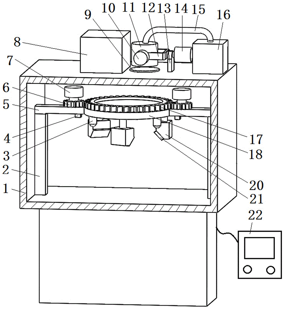
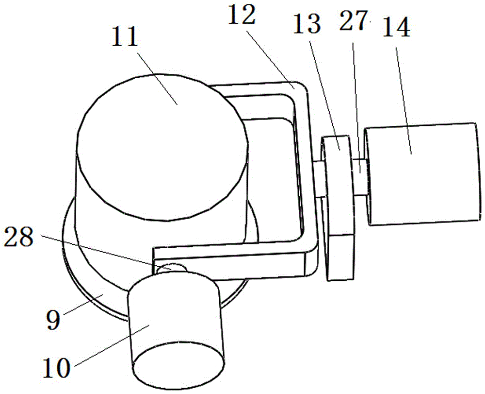
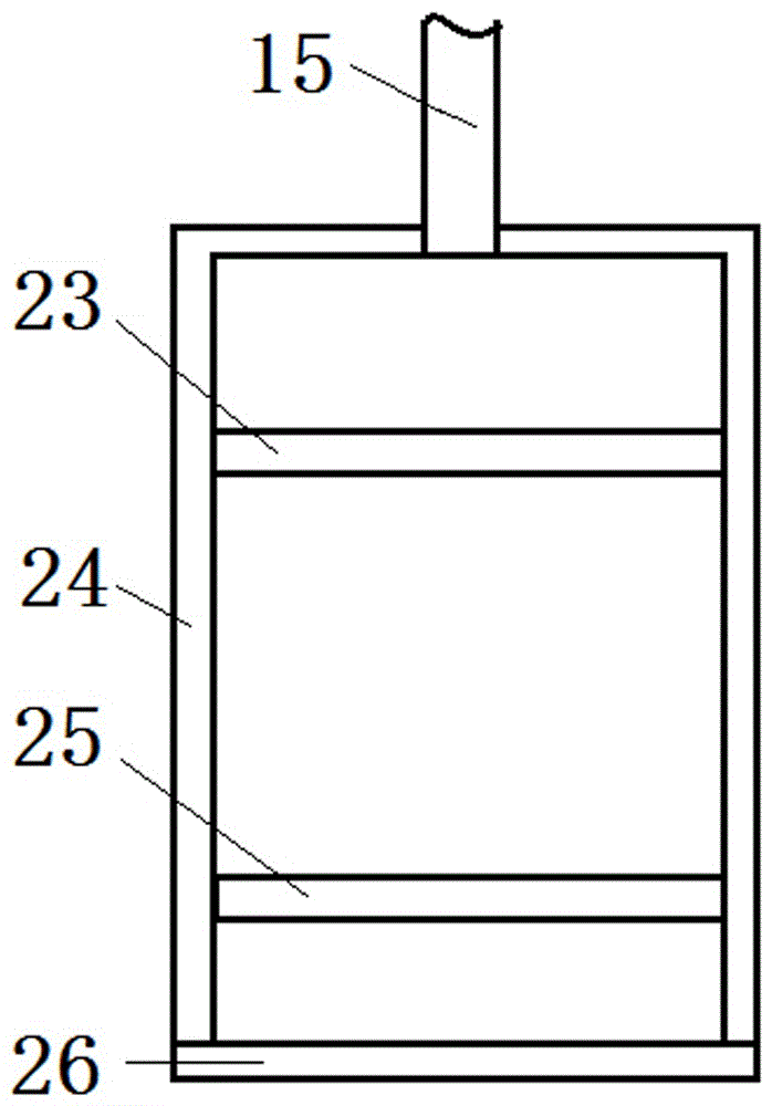
[0023] Such as figure 1 As shown, the selective laser melting and forming molten pool real-time monitoring device includes a forming cavity 1. The top of the forming cavity 1 is provided with a melting forming laser system 8 and a pulse laser 16, and the top center of the forming cavity 1 is provided with a transparent glass 9, transparent glass A laser lens barrel 11 is provided above 9, and a pulse laser 16 is connected to the laser lens barrel 11 through an optical fiber 15. A lifting frame 5 is provided in the molding cavity 1, and a lifting mechanism 2 is provided on both sides of the lifting frame 5. The bottom of the lifting frame 5 Cameras 20 are arranged at multiple angles, and the fusion forming laser system 8, pulse laser 16, lifting mechanism 2 and camera 20 are all connected to the main control system 22.
[0024] The melt forming laser system 8 is used for laser sintering the formed parts, and the pulse laser 16 is used to emit pulsed lasers to cover the arc during the forming process and reduce the intensity of the molten pool radiant light, thereby facilitating the molten pool camera to image the molten pool. The pulse laser 16 is installed on the top of the forming cavity 1. The pulse laser has a laser power of 7.5-12mW, a peak power of 75-90kW, and a pulse duration of 1-2ns in a pulse period. One end of the optical fiber 15 is connected to the pulse laser 16 and the other end is connected to the laser lens barrel 11. Among them, such as figure 2 As shown, the top of the molding cavity 1 is provided with a support bracket 13, and the support bracket 13 is provided with a rotating shaft 27. One end of the rotating shaft 27 is provided with a first motor 14, and the other end is provided with a U-shaped frame 12. The laser lens barrel 11 is hinged on the U-shaped In the frame 12, the hinge shaft 28 of the U-shaped frame 12 is provided with a second motor 10, and the first motor 14 and the second motor 10 are both connected to the main control system 22. The laser lens barrel is installed on the U-shaped frame. The U-shaped frame can be swung back and forth by the first motor, and the laser lens barrel can be driven left and right by the second motor, so that the emitted laser can be scanned in the three-dimensional space. The system 22 controls the movement mechanism of the lens barrel according to the model slice and scanning path, so that the pulse laser can follow the trajectory of the forming laser emitted by the melting and forming laser system, so that the pulse laser can cover the arc during the forming process and reduce the radiation of the molten pool. Strength, so that it is convenient for the molten pool camera system to image the molten pool.
[0025] Such as image 3 As shown, the laser lens barrel 11 includes a barrel 24, a beam expander 23, a focusing lens 25, and a protective lens 26. The top of the barrel 24 is connected to the optical fiber 15, and the bottom of the barrel 24 is provided with a protective lens 26. A beam expander 23 and a focusing lens 25 are sequentially arranged from top to bottom. The beam expander 23 is installed under the optical fiber 15 to expand the beam diameter, reduce the beam divergence angle, and reduce energy loss. A focusing lens 25 is installed below the beam expander 23, and the focusing lens 25 is mainly used to focus the light beam, so that the focused spot obtains a uniform focusing characteristic within the scanning range. A protective lens 26 is installed under the focusing lens, and the protective lens 26 is installed at the bottom of the lens barrel 11 to protect the optical path system such as the focusing lens 25.
[0026] Such as figure 1 with Figure 4 As shown, the center of the lifting frame 5 is provided with an annular support 18, an annular base 17 is rotatably installed in the annular support 18, an annular groove 19 is arranged at the lower part of the annular base 17, and a ring gear 29 is arranged at the upper part, and the annular base 17 passes through the annular groove 29 It is clamped on the ring support 18, the two sides of the ring base 17 are provided with gears 6 meshing with the ring gear, and the gear 6 is provided with a third motor 7. The cameras 20 are evenly fixed on the bottom of the ring base 17, next to each camera 20 An infrared temperature measurement sensor 3 is also provided, and infrared distance measurement sensors 4 are also provided on both sides of the bottom of the ring bracket 18, and the third motor 7, infrared temperature measurement sensor 3 and infrared distance measurement sensor 4 are all connected to the main control system 22 , The lens of the camera 20 is provided with a high temperature resistant protective cover 21.
[0027] In the present invention, the number of cameras and infrared temperature measuring sensors are both three, and the cameras and the infrared temperature measuring sensors are arranged at 120° with each other. The camera and the infrared temperature sensor are both installed on the bottom of the ring base, the ring base is installed on the lifting frame, and the upper part of the ring base is provided with a ring gear that meshes with the gear, so that the lifting mechanism can drive the lifting frame to move up and down, and the third motor can Drive the ring base to rotate, so that the camera and the infrared temperature sensor move accordingly. The lifting mechanism can be a hydraulic lifting mechanism or a mechanical lifting mechanism. The infrared temperature sensor is used to measure the temperature of the molten pool from different directions. The measured temperature data is then transmitted to the main control system 22, and the main control system 22 performs a comparative analysis based on the temperature measurement data and the molten pool image data, so as to further correct the temperature of the molten pool and determine the laser light rate. The infrared distance sensor is used to measure the distance between the camera 20 and the molded part, and feed this information back to the main control system 22. The main control system 22 adjusts the lifting mechanism according to the feedback distance information to keep the camera 20 and the product optimal The camera distance is adjusted according to the laser scanning trajectory of the melting forming laser system 8 to keep the camera and the molten pool at the best camera angle. After the camera shoots the molten pool from different angles, it is transmitted to the main control system 22. The main control system 22 analyzes the shape of the molten pool, the temperature, shape and area of ​​the molten pool, and can perform online evaluation of the laser power to adjust the laser power.
[0028] When performing real-time monitoring, follow the steps below:
[0029] a. Start the forming laser system to make the forming laser emitted to melt the forming powder according to the profile size of the model section;
[0030] b. Start the laser stroboscopic system to use the pulsed laser to emit pulsed lasers. The main control system adjusts the running track of the pulsed laser so that its running track closely follows the running track of the forming laser, and the pulsed laser covers the arc and melting during the forming process. The intensity of the radiant light from the pool;
[0031] c. Adjust the height and camera angle of the molten pool camera to ensure the best camera effect, and feed back the molten pool picture to the main control system. The main control system analyzes the temperature, shape and area of ​​the molten pool and calculates the actual working power of the forming laser , And compare with the set value;
[0032] d. The molten pool infrared temperature sensor measures the temperature of the molten pool from different angles, and transmits the temperature information to the main control system. The main control system compares the molten pool temperature information with the image information of the molten pool to further verify the molten pool Temperature, shape and area, and actual power of the forming laser;
[0033] e. The main control system adjusts the power of the forming laser according to the above information to realize the control of the metal molten pool, thereby realizing the control of the precision and mechanical properties of the formed product.
[0034] The above are only the preferred embodiments of the present invention and are not intended to limit the present invention. Any modification, equivalent replacement and improvement made within the spirit and principle of the present invention shall be included in the scope of the present invention .

PUM

no PUM

Description & Claims & Application Information

We can also present the details of the Description, Claims and Application information to help users get a comprehensive understanding of the technical details of the patent, such as background art, summary of invention, brief description of drawings, description of embodiments, and other original content. On the other hand, users can also determine the specific scope of protection of the technology through the list of claims; as well as understand the changes in the life cycle of the technology with the presentation of the patent timeline. Login to view more.

Similar technology patents

Thick plate rolling method

ActiveCN102886381AImprove the plane shape of the steel plateImprove yieldMetal rolling arrangementsProfile control deviceSteel platesShape control
Owner:BAOSHAN IRON & STEEL CO LTD

Classification and recommendation of technical efficacy words

Why Eureka
Try Eureka