
A self-lubricating low temperature rise harmonic reducer and preparation method thereof

A harmonic reducer and self-lubricating technology, which is applied in the field of mechanical equipment manufacturing, can solve the problems of dry friction, hard cast structure, short life, etc., achieve high acceleration torque and instantaneous acceleration torque, and excellent self-lubrication function , the effect of prolonging life

Active Publication Date: 2019-08-09
许旸 +1
View PDF4 Cites 0 Cited by
  • Summary
  • Abstract
  • Description
  • Claims
  • Application Information

AI Technical Summary

Problems solved by technology

[0004] 1 Due to the needs of elastic deformation, the wall thickness of the flexspline is only about 1-2mm, and because of the limitation of the hardness of the cutting tool, the hardness of the flexspline and the internal tooth rigid spline is only HRC28-32, the strength is low, and the torque is limited. shorter lifespan
[0005] 2. The modulus of the teeth of the flexible wheel and the internal tooth rigid wheel is only 0.1-0.3, and it will slip and be scrapped if it is slightly worn
[0006] 3 Harmonic transmission is mainly realized by the radial deformation of the flex spline. When the flex spline and the internal toothed spline engage at high speed, the slip rate between the tooth surfaces is several times higher than that of ordinary gear transmission. The friction breaks the lubricating oil film, causing dry friction and wear on the tooth surface
However, because the rigid wheel is thicker, the as-cast structure of the inner tooth part is not easy to be fine and dense, so the graphite balls in the tooth part are very large and the density is very small, about 50 / mm 2
Such large and thin graphite balls are easy to cause chipping, and the self-lubricating effect is also limited

Method used


Image

  • A self-lubricating low temperature rise harmonic reducer and preparation method thereof
  • A self-lubricating low temperature rise harmonic reducer and preparation method thereof
  • A self-lubricating low temperature rise harmonic reducer and preparation method thereof

Examples


preparation example Construction

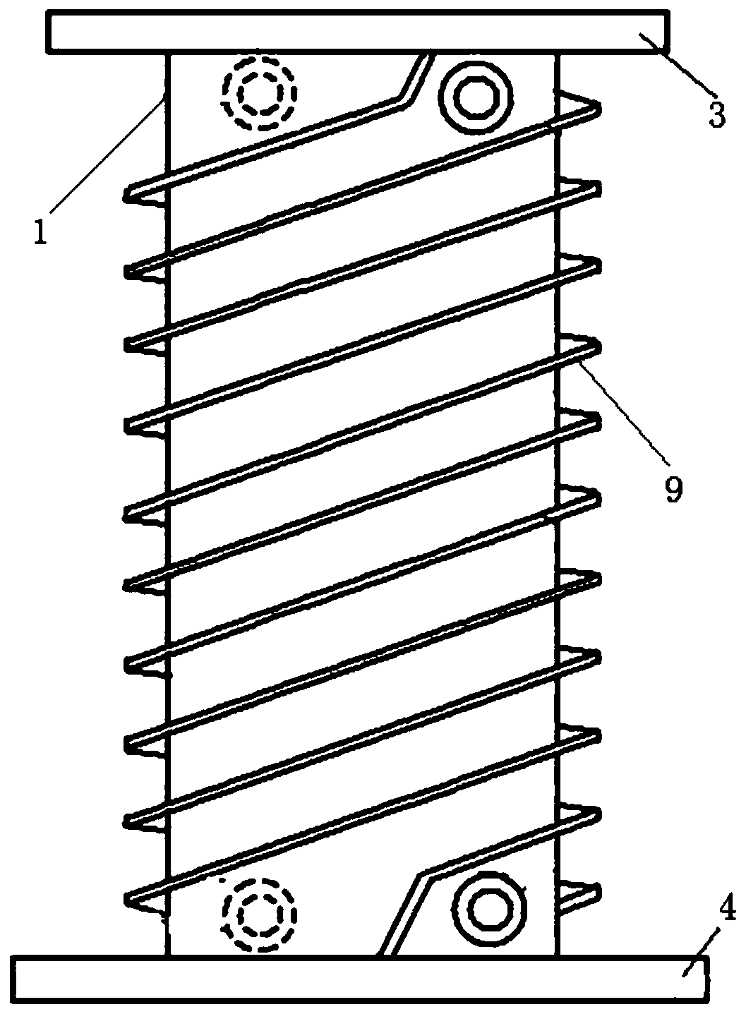
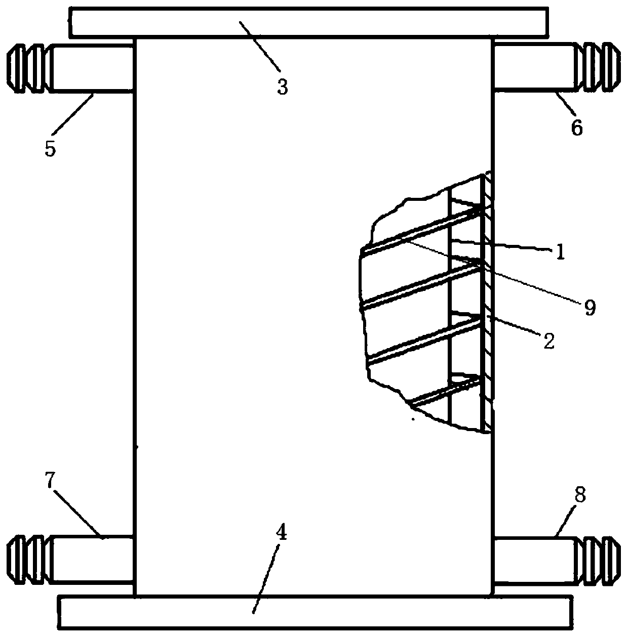
[0049] The present invention also provides a preparation method for the above-mentioned harmonic reducer, which is described in the patent "Continuous Casting Equipment for Low Plasticity Metal Hollow Profiles" (Patent No.: ZL200710018928.2, Publication No.: 101134231, Publication Date: 2008-03- 05) on implementation. The difference with the original device is that the structure of the crystallizer in the original device is different from that of the crystallizer in the present invention, such as Figure 1~2 As shown, its structure is as follows: it includes an inner cylinder 1 and an outer cylinder 2 that are nested with each other. The bottom of the outer cylinder is connected with the lower flange 4, the upper part of the outer cylinder 2 is respectively provided with water inlet I5 and water inlet II6, the lower part of the outer cylinder 2 is respectively provided with water outlet I7 and water outlet II8, and the inner cylinder The outer circle of 1 has a double-helix r...

Embodiment 1

[0078] Step 1, using bread pig iron, scrap steel and ferroalloy materials, configure the molten iron components according to the mass percentage: C: 3.4%-3.7%, Si: 1.5%-1.7%, Mn: 0.3%-0.5%, Cr: 0.3%-0.5% %, S≤0.05%, P≤0.05%, Fe is the balance, the sum of the mass percentages of the above components is 100%, and the above materials are melted into molten iron, and the final silicon content of the molten iron is 2.7 through inoculation and spheroidization %-2.9%, residual magnesium content 0.03%-0.045%;

[0079]Step 2, drawing the molten iron in step 1 into hollow profiles and solid bars respectively by a vertical continuous casting method;

[0080] Step 3, detecting the metallographic structure of the hollow profile obtained in step 2 and the solid bar;

[0081] For the hollow profile of the internal tooth rigid wheel, it is necessary to ensure that the graphite spheroidization rate in the as-cast structure at a depth of 15-20 mm from the surface is ≥ 90%, the diameter of grap...

Embodiment 2

[0097] Step 1, using bread pig iron, scrap steel and ferroalloy materials, configure the molten iron components according to the mass percentage: C: 3.4%-3.7%, Si: 1.5%-1.7%, Mn: 0.3%-0.5%, Cr: 0.3%-0.5% %, S≤0.05%, P≤0.05%, Fe is the balance, the sum of the mass percentages of the above components is 100%, and the above materials are melted into molten iron, and the final silicon content of the molten iron is 2.7 through inoculation and spheroidization %-2.9%, residual magnesium content 0.03%-0.045%;

[0098] Step 2, drawing the molten iron in step 1 into hollow profiles and solid bars respectively by a vertical continuous casting method;

[0099] Step 3, detecting the metallographic structure of the hollow profile obtained in step 2 and the solid bar;

[0100] For the hollow profile of the internal tooth rigid wheel, it is necessary to ensure that the graphite spheroidization rate in the as-cast structure at a depth of 15-20 mm from the surface is ≥ 90%, the diameter of gra...


PUM

PropertyMeasurementUnit
diameteraaaaaaaaaa
Area ratioaaaaaaaaaa
hardnessaaaaaaaaaa

Abstract

The invention discloses a self-lubricating low-temperature-rise harmonic reducer composed of three major parts including an internal tooth rigid gear, a flexible gear and a flexible bearing. Each of the internal tooth rigid gear, the flexible gear and the flexible bearing is made of an austempering ductile iron material (ADI) and has an ultrafine matrix structure and a graphite form. The graphite nodule diameter at the tooth part of the internal tooth rigid gear is smaller than or equal to 0.03mm, and the graphite nodule density is larger than or equal to 200 / mm<2>; the graphite nodule diameters of the flexible gear and a bearing ring are smaller than or equal to 0.02mm, the graphite nodule density is larger than or equal to 400 / mm<2>, and the matrix structure can be clearly observed under a metallurgical microscopy with the magnification of more than 500. The harmonic reducer disclosed by the invention has an excellent self-lubricating function, so that injecting lubricating grease is thoroughly avoided; and the life is prolonged, and meanwhile, the self-lubricating low-temperature-rise harmonic reducer has the advantages of low temperature rise, low noise, light weight, large torque, high rigidity as well as high acceleration torque and transient acceleration torque.

Description

technical field [0001] The invention belongs to the technical field of mechanical equipment manufacturing, and in particular relates to a self-lubricating low-temperature rise harmonic reducer, and also relates to a preparation method of the harmonic reducer. Background technique [0002] The key components for industrial robots to realize mechanical actions are RV reducer and harmonic reducer. Harmonic gear reducer is a precision mechanical device composed of internal gear rigid wheel, flexible wheel and flexible bearing. Accurate and other advantages, plus the materials used are 50% less, volume and weight are reduced by at least 1 / 3, so it is especially suitable for industrial robots. A six-axis robot usually needs to use 3-4 harmonic reducers to realize the deceleration and torque increase function of the 3rd-6th joints, and the market capacity is very large. [0003] In April 2016, the "Robot Industry Development Plan (2016-2020)" jointly issued by the Ministry of Ind...

Claims


Application Information

Patent Timeline
Patent Type & Authority Patents(China)
IPC IPC(8): C22C37/10C21D1/32C21D1/20B22D11/055C21D9/34C21D9/40F16H1/28
CPCB22D11/055C21D1/20C21D1/32C21D9/34C21D9/40C22C37/10F16H1/28
Inventor 许旸
Owner 许旸
Learn More