Method for removing and recycling hydrogen fluoride from hydrogen chloride gas

A technology of hydrogen chloride gas and hydrogen fluoride, applied in the direction of hydrogen fluoride, chlorine/hydrogen chloride, fluorine/hydrogen fluoride, etc., can solve a large amount of fluorine-containing waste water and fluorine-containing solid waste, fluorine resource transfer fee, heavy environmental protection pressure and other problems, and achieve low production cost , easy operation and high defluorination efficiency

Inactive Publication Date: 2017-03-15
CENT SOUTH UNIV
View PDF5 Cites 10 Cited by
  • Summary
  • Abstract
  • Description
  • Claims
  • Application Information

AI Technical Summary

Problems solved by technology

[0006] The traditional method of removing hydrogen fluoride from the by-product hydrogen chloride is to transfer hydrogen fluoride into an aqueous solution, resulting in a large amount of fluorine-containing wastewater and fluorine-containing solid waste, which not only causes a huge waste of fluorine resources, but also brings heavy environmental pressure.

Method used


Image

  • Method for removing and recycling hydrogen fluoride from hydrogen chloride gas

Examples


Embodiment 1

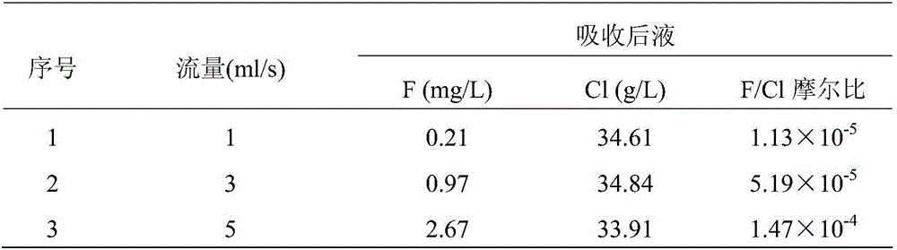
[0038] Use a 250ml plastic flask and a plastic burette to form a simple Kipp generator, and fill the flask with 100g of NaCl and NaF, and fill the Φ25×400 plastic ion exchange column with anhydrous chlorinated Calcium particles 250g, the inlet of the ion exchange column is connected with the gas outlet of the Kipp generator with a plastic hose, and then slowly add concentrated sulfuric acid through the burette to control the gas flow rate of the gas outlet of the Kipp generator to 1-5ml / s, start The gas generated by the general generator passes through the ion exchange column in the way of top in and bottom out, and the residual gas after the adsorption of the ion exchange column is absorbed by NaOH solution. The defluorination test results of different gas flow rates are as follows:

[0039]

Embodiment 2

[0041] Using 2-5mm calcium oxide particles as adsorbent, packing column (Φ500×3000), 6-stage series column, treating anhydrous hydrogen chloride by-product hydrogen chloride gas produced in the preparation process of chlorofluoroalkane in a chemical plant, of which the volume of HF The concentration is 1.5%, and the by-product hydrogen chloride gas passes through the adsorption column at room temperature at 10cm / s. When the volume concentration of HF at the outlet of the first-stage adsorption column reaches 3.5%, the adsorption column is switched, and a blank is connected in series after the sixth-stage adsorption column. Then connect the inlet of the by-product hydrogen chloride gas to the inlet of the second-stage adsorption column, close the gas inlet valve of the first-stage adsorption column, and use an inert gas to eject the residual by-product hydrogen chloride gas in the first-stage adsorption column. , close the gas outlet valve of the first-stage adsorption column, a...


PUM

PropertyMeasurementUnit
particle diameteraaaaaaaaaa

Abstract

Disclosed is a method for removing and recycling hydrogen fluoride from hydrogen chloride gas. The method comprises drying the hydrogen chloride gas containing hydrogen fluoride, and then through calcium / magnesium / aluminum oxide / chloride / hydroxide / carbonate as absorbent, absorbing the hydrogen fluoride contained in the hydrogen chloride gas to obtained defluorinated hydrogen chloride gas and loaded absorbent, wherein the defluorinated hydrogen chloride gas can be directly put into use or absorbed inside water to produce hydrochloric acid for utilization; adding H2SO4 into the loaded absorbent to converted fluorine inside the loaded absorbent into HF, and increasing the temperature to volatize the HF from the reaction system for producing fluorine compounds and further achieving the effect of removing hydrogen fluoride as well as recycling or fluorine resources. The method for removing and recycling the hydrogen fluoride from the hydrogen chloride gas has the advantages of being simple in process and operation, low in production cost, economic, high in efficiency, environmentally-friendly and high in defluorination efficiency, thereby being applicable to industrial application.

Description

technical field [0001] The invention discloses a method for removing hydrogen fluoride from hydrogen chloride gas and recovering hydrogen fluoride, which belongs to the technical field of chemical industry. Background technique [0002] With the rapid development of industrial production and science and technology, the variety and output of organic fluorine products are increasing day by day, especially the demand for fluoropolymers is increasing. The organic fluorine monomer produced by organic synthesis method produces a large amount of by-product hydrogen chloride containing hydrogen fluoride during the preparation process of the initial raw material of chlorofluoroalkane, which greatly limits the utilization value of the by-product hydrogen chloride and makes it difficult to sell. In order to improve the utilization value of by-product hydrogen chloride and broaden its utilization field, people have done a lot of research on the removal of hydrogen fluoride in by-product...

Claims


Application Information

Patent Timeline
Patent Type & Authority Applications(China)
IPC IPC(8): C01B7/07C01B7/19
CPCC01B7/0718C01B7/197
Inventor 王学文王明玉
Owner CENT SOUTH UNIV
Why Eureka
Try Eureka