Method for achieving isolation of semiconductor device

A device isolation and semiconductor technology, which is applied in semiconductor/solid-state device manufacturing, electrical components, circuits, etc., can solve the problems of voids or cracks in trenches, high side profile requirements, etc., and achieve fast filling rate, excellent gap filling ability, low cost effect

Active Publication Date: 2017-03-22
PEKING UNIV
View PDF5 Cites 0 Cited by
  • Summary
  • Abstract
  • Description
  • Claims
  • Application Information

AI Technical Summary

Problems solved by technology

However, HARP-SACVD has high requirements on the filled side profile. Unideal side profiles such as U-shaped grooves will cause voids or cracks inside the grooves. These deficiencies are difficult to improve by improving process conditions

Method used


Image

  • Method for achieving isolation of semiconductor device
  • Method for achieving isolation of semiconductor device
  • Method for achieving isolation of semiconductor device

Examples


Embodiment Construction

[0045] The present invention will be described in detail below with reference to the drawings and specific examples.

[0046] The isolation of nano-scale silicon-based devices can be achieved according to the following steps:

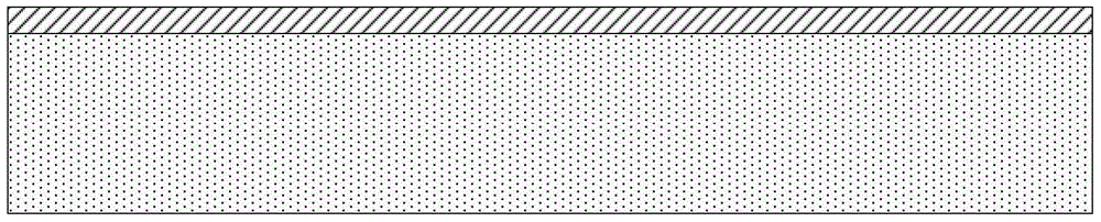
[0047] 1) ALD on (100) bulk silicon substrate SiO 2 , Si 3 N 4 The laminated structure is used as a hard mask layer, such as figure 1 Shown

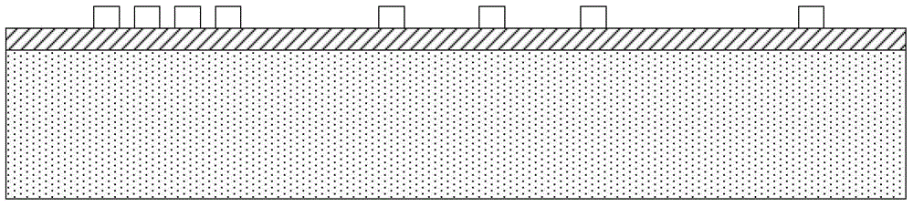
[0048] 2) Electron beam lithography defines the active region window, where the line width is 40nm, the minimum line spacing is 30nm, and the maximum line spacing is 0.5μm. Such as figure 2 Shown

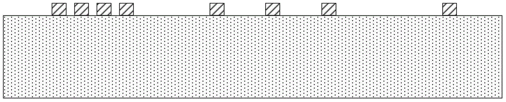
[0049] 3) Anisotropically etch the hard mask layer, and transfer the pattern defined by photolithography to the hard mask, exposing the silicon substrate;

[0050] 4) Remove the photoresist, such as image 3 Shown

[0051] 5) Anisotropic dry etching silicon Transfer the pattern of the hard mask to the silicon substrate to form the active area of ​​silicon, such as Figure 4 Shown

[0052] 6) Dry oxygen oxidation is performed ...


PUM


Abstract

The invention discloses a method for achieving isolation of a semiconductor device. According to the method, a thermal oxidation technology is combined with a deposition technology; an active region of the semiconductor device is firstly formed; a high depth-to-width ratio gap is filled to form narrow STI isolation; and a low depth-to-width ratio gap is finally filled to form wide STI isolation. The method has the advantages that the method has excellent gap filling ability for a micron-scale gap or the high depth-to-width ratio gap with a sub-45nm technology node, the filling quality is good and no hole or crack is generated; the filling rate is high, stable and controllable; an etching damage of an HDP-CVD to a substrate is avoided; and the method does not depend on the shape and form of the section of the gap, and is completely compatible with a bulk silicon CMOS process, simple in process and low in cost.

Description

Technical field [0001] The invention belongs to the technical field of ultra-large-scale integrated circuit manufacturing, and relates to a method for implementing isolation of semiconductor devices in integrated circuits. Background technique [0002] The different technological eras of integrated circuits are marked by the feature sizes of the devices they process. With the rapid development of the integrated circuit industry, the feature sizes of semiconductor devices have shrunk from sub-micron to nano-scale, and the corresponding spacing between devices Has also become extremely small. In Intel's 14nm node process, the spacing between Fin bars is only 42nm. Filling such narrow gaps with high aspect ratio to form device isolation is a big challenge to traditional chemical vapor deposition (CVD) technology. [0003] Because the traditional CVD method has a faster filling rate at the top of the gap than in the middle of the gap, when filling a high aspect ratio gap less than 0.8...

Claims


Application Information

Patent Timeline
Patent Type & Authority Applications(China)
IPC IPC(8): H01L21/762
CPCH01L21/762H01L21/76202H01L21/76224
Inventor 黎明陈珙杨远程樊捷闻张昊黄如
Owner PEKING UNIV
Why Eureka
Try Eureka