Automatic underwater silt remover

A desilting machine and automatic technology, applied in mechanically driven excavators/dredgers, earth movers/shovels, construction, etc., can solve problems such as high cost, easy to damage hard soil layers, and damage the environment, and achieve The effect of high work efficiency, low operation difficulty and high safety factor

Inactive Publication Date: 2017-03-29
NUCLEAR IND YANTAI TONCIN IND GRP CO LTD
View PDF9 Cites 6 Cited by
  • Summary
  • Abstract
  • Description
  • Claims
  • Application Information

AI Technical Summary

Problems solved by technology

[0013] Disadvantages: The mud concentration formed by this method is low, which increases the difficulty for subsequent processing, and the construction environment is relatively harsh, which damages the environment
[0015] The disadvantages of dry water operations are: the construction cost of temporary cofferdams is increased due to the need to drain the running water in the river. At the same time, many rivers can only be constructed in non-flood seasons, and the construction period will be limited. The construction process is easily affected by the weather, and it is easy to damage the river. Damage to slopes and ecosystems
[0022] Disadvantages: The grab dredger is not sensitive to extremely soft bottom mud, and it is easy to leak a large amount of surface bottom mud, especially floating mud, when digging the hard soil at the bottom of the river bed. In general, the sludge removal rate can only reach about 30%. In addition, the grab dredging is prone to floating mud leakage and strong disturbance of the sediment. In the dredging process aimed at improving water quality, it is often impossible to achieve the original level. Purposeful
[0027] Disadvantages: Bucket wheel dredging will produce a large amount of pollutants to diffuse during the dredging project, and the situation of escape and return is serious. The sludge removal rate is about 50%, and the dredging is not thorough enough, which is likely to cause large-scale water pollution
[0032] Disadvantages: Ordinary cutter suction dredging adopts spiral slice reamer for open excavation, which may easily cause the diffusion of pollutants in the sediment, and at the same time, there will be more serious phenomenon of return. According to the experience of existing projects, the sediment The removal rate is about 70%. In addition, the blowing method leads to low sludge concentration, resulting in an increase in the volume of the sludge, which will increase the area occupied by the sludge dump
[0035] (1) The setting of the dredging ship is complicated, and it is necessary to set anchors on the bank or in the river, and cooperate with the rear positioning piles to realize the fan-shaped sweep of the twisting suction head
[0036] (2) Over-excavation and under-excavation are prone to occur when the double piles advance alternately. Every movement of the twisting suction head requires the entire ship to move, and it is extremely difficult for the dredging ship to turn around.
[0037] (3) The technical requirements for the driver’s operation are too high, and the situation of the river bottom cannot be judged in real time. It is difficult for the double piles to advance alternately to keep a straight line, and the trajectory of the twisting suction head is prone to overlap and omission
[0038] (4) The dredging ship is too heavy and can only handle sludge in a specific water depth range, for example, it cannot handle the water depth within 1m
[0039] (5) The cutter suction head of the dredging ship has a maximum excavation depth, which cannot handle deep silt, for example, the water depth below 6m cannot be processed
[0040] (6) Dredging ships have poor sensitivity to silt, especially to soft mud, and are very easy to damage hard soil layers and river beds
[0041] (7) The dredging ship takes the water surface as a reference surface and cannot adapt to changes in the river bed. It either sucks up water empty-handed, or digs the river bed
[0042] (8) The work continuity of the dredging ship is poor, the pile lifting process takes a long time, and the pump sucks clean water
[0043] (9) The equipment is too large to go ashore easily, soaked in water for a long time, and the life is short
[0044] (10) The cost is high, the cost is too high, and the profit is low
[0045] (11) The power is too high, increasing energy consumption
[0046] (12) Cannot be constructed in narrow waters
[0047] (13) It is greatly affected by the mud concentration
[0048] As we all know, the contribution of dredgers to river engineering is very large, and this major project has also been widely used in society. Although the convenience brought by dredgers to water conservancy projects cannot be ignored, but in such a large There are always many disadvantages in the operation of dredgers. With the continuous development of society, existing dredging equipment manufacturers have higher requirements for dredgers, which are mainly reflected in the following points: large dredgers Not only does it bring great inconvenience to the driver in terms of technical application, but also the large body makes it difficult to adjust the rolling direction in the construction range of sludge cleaning, which makes it difficult to fully clean the sludge and the material rate. In addition, the manufacture of large dredgers also increases the cost of the company. The large dredgers are bulky and cannot be easily landed. They are soaked in water for a long time, which seriously shortens their service life.
[0049] The above four major drawbacks of the integrated dredger, the biggest problem is that it is bulky, which leads to a series of problems. After years of research and combined with the existing dredger technology, the applicant proposed a new type of dredger. The automatic desilting machine solves the above problems reasonably

Method used


Image

  • Automatic underwater silt remover
  • Automatic underwater silt remover
  • Automatic underwater silt remover

Examples


Embodiment 1

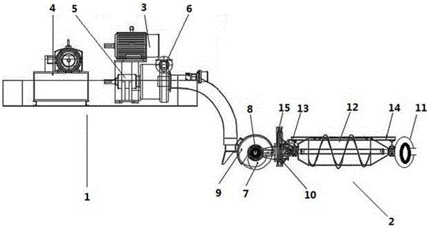
[0084] Embodiment one: figure 1 As shown, the underwater automatic desilting machine is composed of two parts, the above water part 1 and the underwater part 2. The above water part 1 and the underwater part 2 are connected extensibly by mud pipes, hydraulic pipes and hoisting ropes. The above water part 1 includes a mud pump 3, a hydraulic station 4, a small air pump 5, a generator (not shown in the figure), a winch 6 and a control system, and the underwater part 2 includes a collection transfer device 7, a collection motor 8 , Collecting shield 9, collecting hoisting device 10, collector 11 and propeller 12, said collector 11 is hinged with propeller 12, and said propeller 12 adopts hollow structure.

[0085] The propeller 12 is provided with a counterweight device 13, and the counterweight device 13 can drive the underwater part to float up and down in the water. It can realize dredging for different geographical environments, and it is convenient to climb and descend slop...

Embodiment 2

[0090] Embodiment two: figure 1 As shown, the underwater automatic desilting machine is composed of two parts, the above water part 1 and the underwater part 2. The above water part 1 and the underwater part 2 are connected extensibly by mud pipes, hydraulic pipes and hoisting ropes. The above water part 1 includes a mud pump 3, a hydraulic station 4, a small air pump 5, a generator (not shown in the figure), a winch 6 and a control system, and the underwater part 2 includes a collection transfer device 7, a collection motor 8 , Collecting shield 9, collecting hoisting device 10, collector 11 and propeller 12, said collector 11 is hinged with propeller 12, and said propeller 12 adopts hollow structure.

[0091] The propeller 12 is provided with a counterweight device 13, and the counterweight device 13 can drive the underwater part to float up and down in the water. It can realize dredging for different geographical environments, and it is convenient to climb and descend slop...

Embodiment 3

[0096] Embodiment three: figure 1 As shown, the underwater automatic desilting machine is composed of two parts, the above water part 1 and the underwater part 2. The above water part 1 and the underwater part 2 are connected extensibly by mud pipes, hydraulic pipes and hoisting ropes. The above water part 1 includes a mud pump 3, a hydraulic station 4, a small air pump 5, a generator (not shown in the figure), a winch 6 and a control system, and the underwater part 2 includes a collection transfer device 7, a collection motor 8 , Collecting shield 9, collecting hoisting device 10, collector 11 and propeller 12, said collector 11 is hinged with propeller 12, and said propeller 12 adopts hollow structure.

[0097] The propeller 12 is provided with a counterweight device 13, and the counterweight device 13 can drive the underwater part to float up and down in the water. It can realize dredging for different geographical environments, and it is convenient to climb and descend sl...


PUM


Abstract

The invention relates to an automatic underwater silt remover, and belongs to the field of underwater silt removing. The automatic underwater silt remover is composed of two portions including a water portion (1) and an underwater portion (2); the water portion (1) and the underwater portion (2) are in telescopic flexible connection; the water portion (1) comprises a silt pump (3), a hydraulic station (4), a small air pump (5), a winch (6) and a control system; the underwater portion (2) comprises a material collection transfer device (7), a material collection motor (8), a material collection protection cover (9), a material collection lifting device (10), a material collection device (11) and a propeller (12); the material collection device (7) is hinged to the propeller (12), and the propeller (12) is of a hollow structure. The problems that in the prior art, silt removing is not thorough, and the silt removing depth is limited are solved, and the silt remover is mainly applied to large deep underwater silt removing work.

Description

technical field [0001] The invention relates to the technical field of underwater dredging, in particular to an underwater dredging machine. Background technique [0002] With the acceleration of the modernization process, urban rivers are facing great challenges. The rivers become shallower, and the flood storage capacity decreases, which endangers urban safety. At present, most of the bottom of the rivers are deposited with silt, which occupies a large amount of water space in the rivers. When the flood peak passes, It often occurs that the water level is too high and the river flows back into the city, which seriously endangers the safety of the city. The river channel became shallower, weeds overgrown, and the water body became shallower. It becomes smaller, turbid, and overgrown with weeds, affecting the image of the city. The smell is pungent, bacteria breed, and the rich organic matter in the sludge decomposes to release toxic and harmful substances such as ammonia ...

Claims


Application Information

Patent Timeline
Patent Type & Authority Applications(China)
IPC IPC(8): E02F3/88E02F5/28E02F3/90
CPCE02F3/8833E02F3/8875E02F3/907E02F5/282
Inventor 龚景仁冯庸蒋丰丞林炳义李斌王胜毅沈忠良范庆雨
Owner NUCLEAR IND YANTAI TONCIN IND GRP CO LTD
Why Eureka
Try Eureka