
An Optimization Method for 1×n Demultiplexer/Combiner

An optimization method and combiner technology, applied in design optimization/simulation, special data processing applications, etc., can solve problems such as high production process accuracy requirements and complex structure, and achieve the effect of avoiding poor optimization results

Active Publication Date: 2020-04-24
SOUTHEAST UNIV
View PDF5 Cites 0 Cited by
  • Summary
  • Abstract
  • Description
  • Claims
  • Application Information

AI Technical Summary

Problems solved by technology

However, the structure generated by the reverse design method is very complex, and there are many irregularly shaped air holes on the silicon substrate, which requires high precision in the production process

Method used


Image

  • An Optimization Method for 1×n Demultiplexer/Combiner
  • An Optimization Method for 1×n Demultiplexer/Combiner
  • An Optimization Method for 1×n Demultiplexer/Combiner

Examples


Embodiment 1

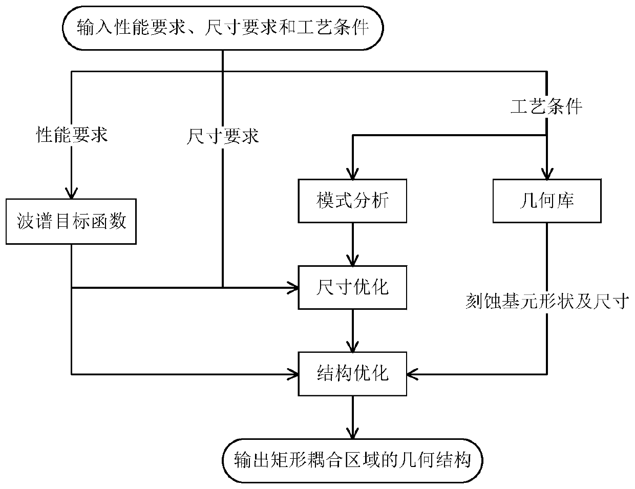
[0033] A method for optimizing a 1×N demultiplexer / combiner, which is applied to the optimization of a 1×21310nm / 1550nm demultiplexer / combiner, comprising the following steps:

[0034] Step 1 Determine the performance requirements, size requirements and process conditions of the 1×21310nm / 1550nm wavelength demultiplexer, the performance requirements are at 1310nm and 1550nm wavelengths, when the power input to the input port is unit power, the output to the output port 1 target power a 11 and a 12 1 and 0, respectively, the target power output to output port 2 a 21 and a 22 are 0 and 1 respectively; the size requirement is the maximum size of the rectangular coupling area, where the maximum length L of the rectangular coupling area max 5000μm, maximum width W max is 50 μm; the process conditions include two parts, the first part is the refractive index of each part of the waveguide, where the substrate refractive index n s is 1.4444, the core refractive index n o is 1.46...


PUM


Abstract

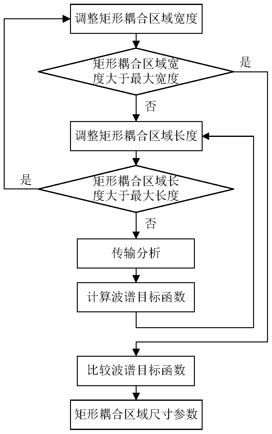
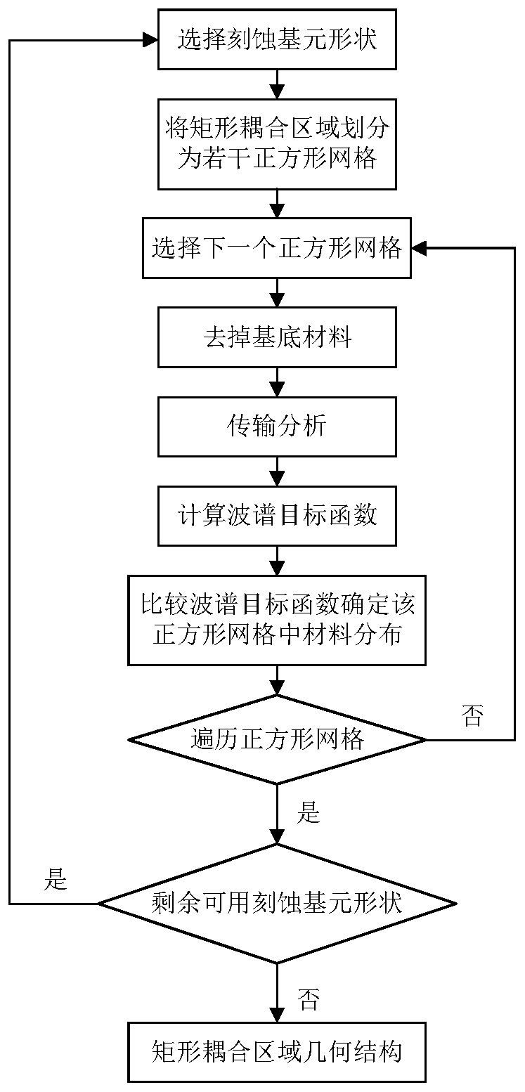
The invention discloses a method for optimizing a 1×N demultiplexer / combiner, comprising: step 1 determining the performance requirements, size requirements and process conditions of the 1×N demultiplexer / combiner, and step 2 using the finite element method to model Analysis, determine the width of the input and output waveguides and the initial width of the rectangular coupling area, select the shape and size of the available etching primitives from the geometry library, step 3 determine the optimal size parameters and optimization times of the rectangular coupling area, and optimize each The rectangular coupling area under the size parameter is optimized, and then the value of the spectral objective function is calculated, and the optimized size parameter with the smallest value of the spectral objective function is used as the size parameter of the rectangular coupling area. Step 4. According to the shape and size of the available etching primitive, the The rectangular coupling area is divided into several square grids, and the processing scheme of each square grid is determined from right to left and from the middle to both sides on the rectangular coupling area, and finally the geometric structure of the rectangular coupling area is determined.

Description

technical field [0001] The invention belongs to the field of photonic device design and relates to an optimization method for a 1×N wave splitter / multiplexer. Background technique [0002] Traditional photonic devices include directional couplers, multimode interference couplers, distributed Bragg reflectors, microring resonators, and grating couplers, etc. At present, most of these photonic devices are manually designed according to the designer's professional knowledge and intuition, the parameter space that can be adjusted is small, and large-scale automated design cannot be performed. [0003] The existing optimization algorithms for photonic device design include genetic algorithm, particle swarm optimization algorithm and level set algorithm. These optimization algorithms are mainly used to fine-tune the existing structure, but cannot replace the designer for structural design. [0004] In order to expand the parameter space of the design, a method of reverse design i...

Claims


Application Information

Patent Timeline
Patent Type & Authority Patents(China)
IPC IPC(8): G06F30/20
CPCG06F30/20
Inventor 孙小菡管孟文蒋卫锋
Owner SOUTHEAST UNIV
Learn More