
Production technology of thionyl chloride

A thionyl chloride and production process technology, which is applied in the production process of thionyl chloride, can solve the problems of reduced safety performance of the device, failure to condense tail gas, material loss, etc., and achieve the effects of small heat loss, improved safety, and reduced use

Active Publication Date: 2017-05-10
SHANDONG KAISHENG NEW MATERIALS
View PDF5 Cites 2 Cited by
  • Summary
  • Abstract
  • Description
  • Claims
  • Application Information

AI Technical Summary

Problems solved by technology

[0004] During the preparation of thionyl chloride, the crude sulfur oxychloride in the gas phase from the reactor is condensed and sulfur mixed, and then the liquid phase is rectified, while the gas phase is recycled back to the reaction system; at the same time, the tail gas generated in the rectification process is condensed and then recycled to the reaction system. Reaction system, but it cannot condense all the tail gas, resulting in a certain material loss. The tail gas that has not been cooled needs to be emptied after water absorption and alkali absorption treatment. The process is relatively complicated and causes material loss; at the same time, too many condensers are used. The safety performance of the device is greatly reduced; the crude thionyl chloride is condensed and then gasified to cause a certain amount of steam consumption, and corresponding power equipment needs to be equipped with high energy consumption

Method used


Image

  • Production technology of thionyl chloride

Examples


Embodiment 1

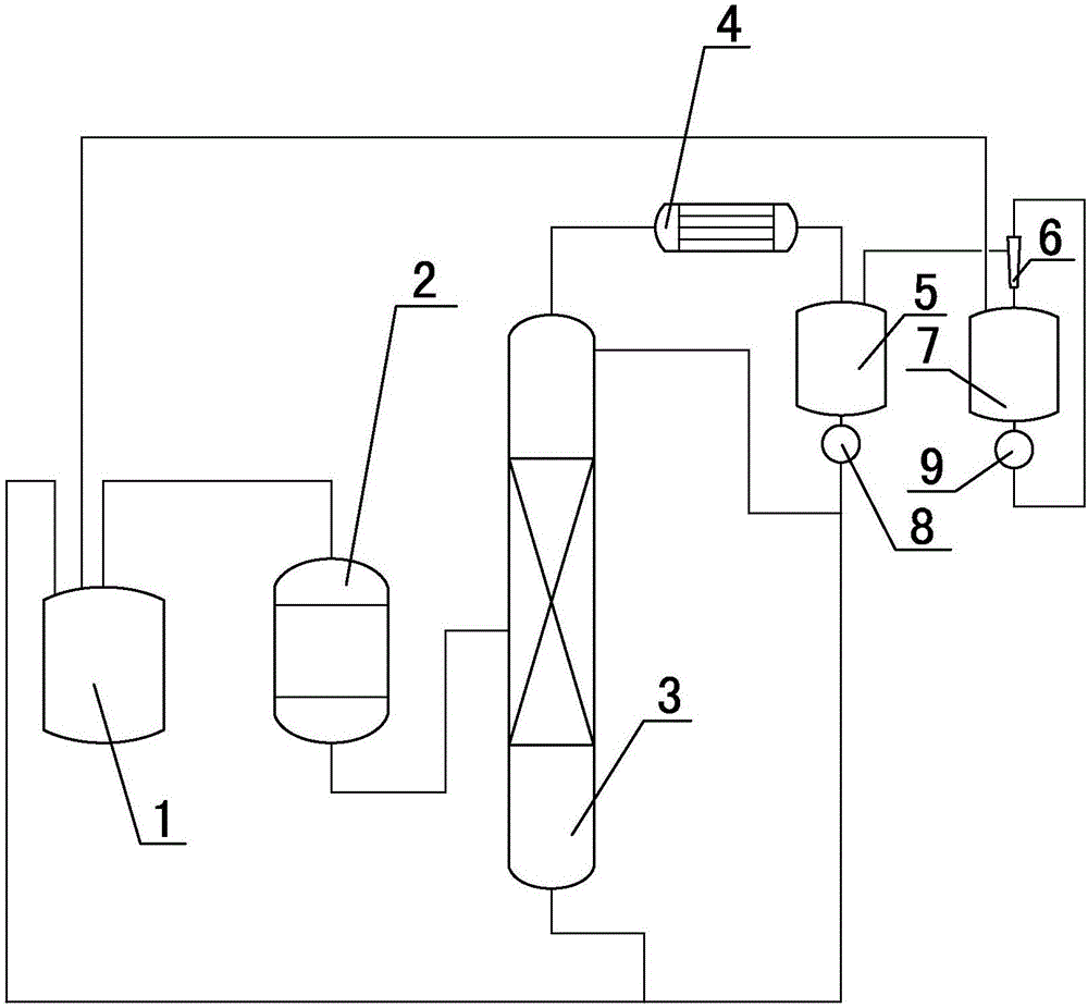
[0020] (1) The synthesis gas produced by the reaction of sulfur and chlorine in the synthesis kettle enters the reactor together with sulfur dioxide gas, and the crude product thionyl chloride generated by the reaction in the reactor directly enters the rectification tower in gaseous form, and the recombination produced at the bottom of the rectification tower The sub-circulation is applied back to the synthesis kettle, and the gas phase at the top of the rectification tower enters the reflux tank after being condensed;

[0021] (2) Part of the liquid phase in the reflux tank is pumped to the rectifying tower to reflux through the first machine pump, and the remaining liquid phase in the reflux tank is taken out and used as a synthesis kettle; the volume ratio of part of the liquid phase to the remaining liquid phase is 10:1;

[0022] (3) The gas phase in the reflux tank enters the evacuation tank through the injector and then circulates back to the synthesis kettle, and the qu...

Embodiment 2

[0024] (1) The synthesis gas produced by the reaction of sulfur and chlorine in the synthesis kettle enters the reactor together with sulfur dioxide gas, and the crude product thionyl chloride generated by the reaction in the reactor directly enters the rectification tower in gaseous form, and the recombination produced at the bottom of the rectification tower The sub-circulation is applied back to the synthesis kettle, and the gas phase at the top of the rectification tower enters the reflux tank after being condensed;

[0025] (2) Part of the liquid phase in the reflux tank is pumped to the rectifying tower to reflux through the first machine pump, and the remaining liquid phase in the reflux tank is taken out and used as a synthesis kettle; the volume ratio of part of the liquid phase to the remaining liquid phase is 4:1;

[0026] (3) The gas phase in the reflux tank enters the evacuation tank through the injector and then circulates back to the synthesis kettle, and the qua...

Embodiment 3

[0028] (1) The synthesis gas produced by the reaction of sulfur and chlorine in the synthesis kettle enters the reactor together with sulfur dioxide gas, and the crude product thionyl chloride generated by the reaction in the reactor directly enters the rectification tower in gaseous form, and the recombination produced at the bottom of the rectification tower The sub-circulation is applied back to the synthesis kettle, and the gas phase at the top of the rectification tower enters the reflux tank after being condensed;

[0029] (2) Part of the liquid phase in the reflux tank is pumped to the rectifying tower to reflux through the first machine pump, and the remaining liquid phase in the reflux tank is taken out and used as a synthesis kettle; the volume ratio of part of the liquid phase to the remaining liquid phase is 6:1;

[0030] (3) The gas phase in the reflux tank enters the evacuation tank through the injector and then circulates back to the synthesis kettle, and the qua...


PUM


Abstract

The present invention relates to the technical field of chemical industry production and in particular relates to a production technology of thionyl chloride. Sulfur and chlorine gas are reacted in a synthesis reactor to produce synthesis gas, the synthesis gas and sulfur dioxide gas enter together into a reactor, produced crude products of the thionyl chloride after the reaction in the reactor directly enter into a distillation column in a gas state, and gas phase from the top of the distillation column is condensed, the condensed gas enters into a reflux tank; and gas phase in the reflux tank enters into an evacuation tank via an ejector, the treated gas is recycled into the synthesis reactor, and qualified products are collected at the middle part of the distillation column. The production technology is simplified and the technologies of condensation, sulphur combining, light component recycling, etc. of the reacted crude products of the thionyl chloride are saved. Due to the reduction of the condensation and regasification, the technology is relatively short in routes and minimal in heat loss, and greatly reduces energy consumptions of the devices.

Description

technical field [0001] The invention belongs to the technical field of chemical production, and in particular relates to a production process of thionyl chloride. Background technique [0002] ZL95110380.6 discloses a manufacturing method of thionyl chloride, the method is to put the crude thionyl chloride obtained by cooling the thionyl chloride prepared by catalytic synthesis into the distillation still with sulfur powder added in advance, Distillation to obtain liquid thionyl chloride product. [0003] According to literature, in the preparation process of thionyl chloride, the crude thionyl chloride synthesized by the reactor is condensed and then subjected to batch rectification or rectification of two-stage rectification tower / three-stage rectification tower. [0004] During the preparation of thionyl chloride, the crude sulfur oxychloride in the gas phase from the reactor is condensed and sulfur mixed, and then the liquid phase is rectified, while the gas phase is re...

Claims


Application Information

Patent Timeline
Patent Type & Authority Applications(China)
IPC IPC(8): C01B17/45
CPCC01B17/4584
Inventor 谢圣斌周勇张良张善民孙丰春王荣海刘嵩毕义霞王鑫海张泰铭
Owner SHANDONG KAISHENG NEW MATERIALS
Learn More