Supply hydraulic station device for carbon tetrachloride treatment and operating method thereof

A technology of carbon tetrachloride and hydraulic station, which is applied in the direction of fluid pressure actuation device, fluid pressure actuation system test, fluid pressure actuation system safety, etc. It can solve problems such as work difficulty, wear of hydraulic components of oil pump, failure to dissipate heat, etc. , to achieve the effect of high degree of automation, simple device structure and convenient operation for employees

Active Publication Date: 2017-05-10
XUZHOU UNIV OF TECH
View PDF9 Cites 3 Cited by
  • Summary
  • Abstract
  • Description
  • Claims
  • Application Information

AI Technical Summary

Problems solved by technology

[0004] 1. The heat dissipation problem of the hydraulic station: the hydraulic station is placed in the pit, and it will not be able to dissipate heat during work. If the oil temperature is too high, the viscosity of the hydraulic oil will decrease. Due to the decrease in viscosity, the sealing strength of all sealing links in the hydraulic system will decrease. , there will be oil leakage and oil leakage, which will also aggravate the wear of the oil pump and other hydraulic components, and increase the power consumption of the oil pump motor;
[0005] 2. The daily operation and observation of the hydraulic station: Since the hydraulic station is placed in the pit and covered with a cover plate, it is impossible to observe whether the hydraulic station is working normally. In addition, this kind of hydraulic station is generally equipped with manual / automatic If there is a sudden failure during work, it is impossible to quickly control the equipment manually;
[0006] 3. Cleaning and maintenance of the hydraulic station: According to conventional requirements, the hydraulic oil must be filtered frequently, and the hydraulic tank must be thoroughly cleaned. In addition, the hydraulic station must also be inspected and maintained regularly, and the hydraulic station should be discharged The pit will not have much space, so it will bring great difficulties to the above work

Method used


Image

  • Supply hydraulic station device for carbon tetrachloride treatment and operating method thereof
  • Supply hydraulic station device for carbon tetrachloride treatment and operating method thereof
  • Supply hydraulic station device for carbon tetrachloride treatment and operating method thereof

Examples


Embodiment 1

[0065] Manufacture filter screen 8-2 of the present invention according to the following steps, and in parts by weight:

[0066] Step 1: Add 1374 parts of ultrapure water with a conductivity of 2.24μS / cm into the reactor, start the stirrer in the reactor at a speed of 64rpm, start the heating pump, and increase the temperature in the reactor to 44°C; add in sequence 64 parts of methyl 2-{[(tert-butoxy)carbonyl]amino}-4-methanesulfonyl butanoate, 2-methyl-2-acrylic acid-4-[methyl(undecafluoropentyl)sulfonyl 54 parts of amino]butyl ester, 94 parts of 2-acrylic acid-2-[[(heptadecafluorooctyl)sulfonyl]methylamino]ethyl ester, stir until completely dissolved, adjust the pH value to 3.4, and turn the stirrer speed Adjust to 134rpm, the temperature is 94°C, and the esterification reaction takes 14 hours;

[0067] Step 2: Take 14 parts of polymers of 2-ethylhexyl acrylate and methyl methacrylate, 2-acrylamido-2-methylpropanesulfonic acid and methacrylic acid, 4-(4-chloro- 74 parts o...

Embodiment 2

[0072] Manufacture filter screen 8-2 of the present invention according to the following steps, and in parts by weight:

[0073] Step 1: Add 1644 parts of ultrapure water with a conductivity of 4.24μS / cm into the reactor, start the stirrer in the reactor at a speed of 124rpm, start the heating pump, and raise the temperature in the reactor to 74°C; add in order 124 parts of methyl 2-{[(tert-butoxy)carbonyl]amino}-4-methanesulfonylbutanoate, 2-methyl-2-acrylic acid-4-[methyl(undecafluoropentyl)sulfonyl Amino] butyl ester 154 parts, 2-acrylic acid-2-[[(heptadecafluorooctyl) sulfonyl] methyl amino] ethyl ester 214 parts, stir until completely dissolved, adjust the pH value to 6.4, and the stirrer speed Adjust to 254rpm, the temperature is 134°C, and the esterification reaction takes 24 hours;

[0074] Step 2: Take 54 parts of polymers of 2-ethylhexyl acrylate and methyl methacrylate, 2-acrylamido-2-methylpropanesulfonic acid and methacrylic acid, 4-(4-chloro- 134 parts of 5,6-d...

Embodiment 3

[0079] Manufacture filter screen 8-2 of the present invention according to the following steps, and in parts by weight:

[0080] Step 1: Add 1444 parts of ultra-pure water with a conductivity of 3.24μS / cm into the reactor, start the stirrer in the reactor at a speed of 94rpm, start the heating pump, and raise the temperature in the reactor to 64°C; add in sequence 84 parts of methyl 2-{[(tert-butoxy)carbonyl]amino}-4-methanesulfonyl butanoate, 2-methyl-2-acrylic acid-4-[methyl(undecafluoropentyl)sulfonyl Amino] butyl ester 134 parts, 2-acrylic acid-2-[[(heptadecafluorooctyl) sulfonyl] methyl amino] ethyl ester 184 parts, stir until completely dissolved, adjust the pH value to 4.4, turn the stirrer speed Adjust to 194rpm, the temperature is 114°C, and the esterification reaction takes 19 hours;

[0081] Step 2: Take 34 parts of polymers of 2-ethylhexyl acrylate and methyl methacrylate, 2-acrylamido-2-methylpropanesulfonic acid and methacrylic acid, 4-(4-chloro- 84 parts of 5,...


PUM


Abstract

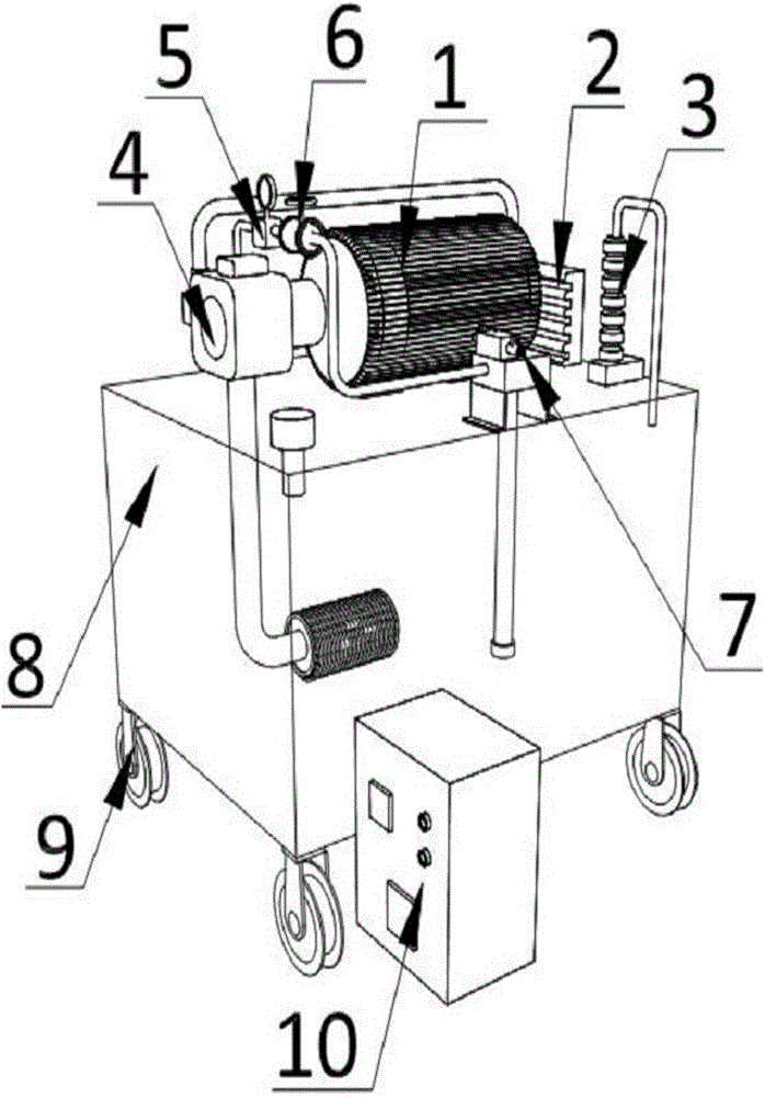
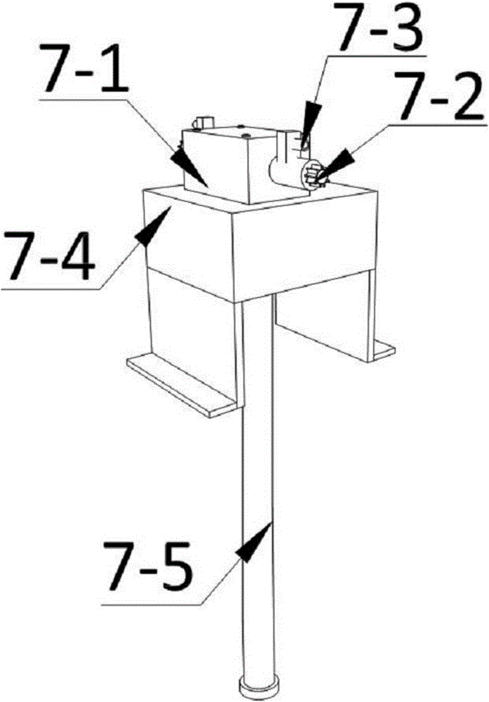
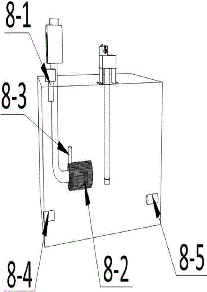
The invention discloses a supply hydraulic station device for carbon tetrachloride treatment and an operating method thereof. The supply hydraulic station device for carbon tetrachloride treatment is formed by an oil pumping motor, a fan cooler, a hydraulic lifting piston, an oil injection pump, a pressure measurement meter, a proportional flow regulator, an oil return mechanism, an oil supply tank, universal wheels and a control system. The oil pumping motor is fixedly arranged in the middle above the oil supply tank; the oil injection pump is located at one side of the oil pumping motor; the oil return mechanism is placed on the front side above the oil supply tank; the pressure measurement meter is connected onto a pipeline of the oil injection pump in a penetrating way; the proportional flow regulator is arranged at one side of the pressure measurement meter; the hydraulic lifting piston is located at the other side of the oil pumping motor; and the fan cooler is placed on the rear side above the oil supply tank. According to the supply hydraulic station device for carbon tetrachloride treatment provided by the invention, the device and a hydraulic use device are used in a separating way, and the device is provided with precise electronic devices such as the pressure meter and the flow regulator so as to accurately control oil pressure and oil liquid usage amount, is high efficient, fast, simple in structure and convenient to transport, and is applicable to various construction conditions.

Description

technical field [0001] The invention belongs to the application field of carbon tetrachloride treatment equipment, and in particular relates to a supply hydraulic station device in carbon tetrachloride treatment and a working method thereof. Background technique [0002] The hydraulic stations used in the carbon tetrachloride treatment industry all need a hydraulic system that provides the power source for its hydraulic cylinder movement. The hydraulic components on the hydraulic station are under the control of electrical components and realize various different The pressure curve is designed to meet the pressure curve requirements of various products, raw materials and production processes. [0003] The production line of the hydraulic station adopts a T-shaped process layout. Due to the limitation of the T-shaped process layout, there is no extra space for the hydraulic station next to the multiple hot presses lined up. The traditional hot press is that each press The pr...

Claims


Application Information

Patent Timeline
Patent Type & Authority Applications(China)
IPC IPC(8): F15B11/00F15B13/02F15B19/00F15B20/00F15B21/02F15B21/04
CPCF15B11/00F15B13/02F15B19/00F15B20/00F15B21/02F15B21/041F15B21/042F15B2211/20515F15B2211/615F15B2211/62F15B2211/857F15B2211/86
Inventor 梁峙梁骁
Owner XUZHOU UNIV OF TECH
Why Eureka
Try Eureka