Power motor with circumferential windings and new energy electromobile

A winding and power technology, which is applied in the field of power motors and new energy electric vehicles, can solve the problems of reducing motor reliability, magnetic field utilization rate, and insulation reliability, etc., to save copper and cost, improve power and efficiency, The effect of improving the utilization rate of the magnetic field

Pending Publication Date: 2017-05-10
杨明
View PDF4 Cites 9 Cited by
  • Summary
  • Abstract
  • Description
  • Claims
  • Application Information

AI Technical Summary

Problems solved by technology

[0005] 1. There are more flux leakage at the end, the utilization rate of the magnetic field is reduced, and the power and efficiency of the motor are affected
[0006] 2. The magnetic flux leakage at the end leads to large eddy current loss in the metal parts near the end, and the temperature rise of the metal device is high. Some specific motors have to take corresponding cooling measures, which increases the cost and failure rate, and reduces the reliability of the motor. sex
[0007] 3. At the same time, the end produces resistive power consumption and generates heat, which increases the copper loss and temperature of the winding, and wastes energy
[0008] 4. The existence of the end makes the length of the winding longer and the amount of electromagnetic wire is larger, which increases the copper material and cost requirements
[0009] 5. The existence of the end also increases the volume and weight of the motor
[0010] 6. The structure of the magnetic core slot in the prior art makes it difficult to insert the winding wire, the winding and inserting process is more complicated, and the space at both ends of some motors is relatively narrow. rising costs
[0011] 7. In order to improve the slot full rate, the insulating paper or the insulating varnish layer used between the magnetic core and the winding, or between the winding and the winding is relatively thin, and the distance between the end of some motor windings and the shell or end cover is relatively close , These places are prone to extrusion, damage, etc., which lead to insulation layer breakdown, ground leakage and other problems
[0012] 8. Most of the general windings have an approximately elliptical structure, and the most effective straight conductor part is often bent, dislocated or cross-layer extrusion due to assembly process problems after being embedded in the slot. Similarly, cross-layer extrusion is also prone to occur at the end Phenomenon, which reduces the reliability of the insulation, is more prone to turn-to-turn, phase-to-phase short circuit or leakage, and increases the failure rate of the motor; the straight conductor part in the slot produces bending, misalignment or misalignment extrusion problems, which will also distort the magnetic field waveform. affect the performance of the motor
[0013] 9. The number of phases of the traditional axial slot embedded wire motor is fixed once the design scheme is determined and cannot be adjusted
[0014] Another important aspect is that the motors currently used in new energy electric vehicles include: AC motors, permanent magnet motors, switched reluctance motors, etc. These motors generally still use the traditional motor structure with end windings. The above-mentioned shortcomings have caused the development of electric vehicles to be largely restricted by the existing motor technology; under the current technical conditions of vehicle power batteries, in the face of increasingly stringent energy-saving and environmental protection technical indicators, how to improve the efficiency of the motor And the problem of improving the reliability of the motor has become a key technical bottleneck restricting the development of electric vehicles. Therefore, it is urgent to develop new motors with high efficiency, energy saving and high reliability.

Method used


Image

  • Power motor with circumferential windings and new energy electromobile
  • Power motor with circumferential windings and new energy electromobile
  • Power motor with circumferential windings and new energy electromobile

Examples


Embodiment 1

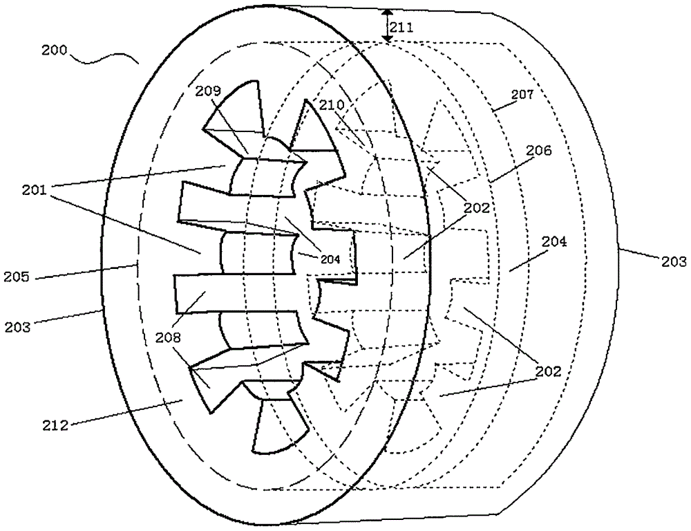
[0141] The description in this embodiment is for illustration: the stator structure, the circumferential winding and the rotor structure of the circumferential winding motor.

[0142] Such as figure 1 As shown, it is a three-dimensional structural diagram of a single-phase stator of a circumferential winding motor. There are 8 pairs of magnetic poles in the circumference of the stator core 200. The magnetic poles can be salient poles. Each pair of convex poles facing in the axial direction The pole is 1 "magnetic pole pair", such as the magnetic pole 209 and the magnetic pole 210 are 1 magnetic pole pair, and the magnetic pole pair is the "teeth" of the motor stator (the left magnetic pole 201, the right magnetic pole 202, etc. in the figure), There are axial slots between two adjacent magnetic poles along the circumferential direction of the stator. The "axial slots" are the "tooth pitch", that is, the magnetic pole spacing, which is called "magnetic pole pitch" (hereinafter ...

Embodiment 2

[0158] The description of this embodiment is for illustration: an axial field motor with a single-phase circumferential winding.

[0159] Such as Figure 8 As shown, it is a side sectional structural schematic diagram of an axial field motor with single-phase circumferential winding, wherein the stator core 230 has a circumferential inner ring groove 235, and the notches are evenly distributed on the circumferential portion 234 on both sides of the 236 There are stator magnetic poles (such as 231, 232), two magnetic poles facing axially form a magnetic pole pair such as 231 / 232 magnetic pole pairs, and the inner ring groove 235 is equipped with a circumferential stator winding 223; the main part of the stator core 230 includes The stator core yoke circumference 233 and the stator pole pairs 231 and 232 can establish an axial magnetic field; the rotor pole 401 on the rotor 400 extends into the space between the stator poles 231 and 232 in the slot, and the rotor pole 401 is con...

Embodiment 3

[0161] The description of this embodiment is for illustration: a side stator type axial field motor with single-phase circumferential winding.

[0162] Such as Figure 9 As shown, it is a side sectional structure schematic diagram of a side stator type axial field motor with single-phase circumferential winding. The circumferential groove is a side ring groove, and a circumferential winding 245 is embedded in the groove. An insulating bracket 243 is provided between the circumferential winding 245 and the side ring groove of the stator. The end leads of the circumferential winding 245 can be placed in the stator Magnetic core drilling etc. lead out; the notch 244 of the side ring groove faces the direction of the stator magnetic pole (shown as the direction to the right), and the inner circumference of the notch 246 is evenly distributed with salient pole type stator magnetic poles (such as the stator magnetic pole 242 ), the circumference of the outer circumference 247 of th...


PUM


Abstract

A power motor with circumferential windings is a switch reluctance type brushless motor composed of a stator, a rotor and an electronic control system; the rotor comprises three rotor magnetic poles as 436, 437 and 438 which are 120 degree from one another; the stator comprises a stator magnetic core and the circular circumferential windings; the stator magnetic core includes three circumferential grooves vertical to the axial and radial directions, and the circumferential windings 311, 312 and 313 are placed in the grooves respectively, three stator magnetic-pole pairs as 284, 285 and 286 are distributed uniformly at the two sides of notches in an aligned manner respectively, and magnetic pole distances between adjacent magnetic poles are as 287, 288 and 289. Stator sequential phase-splitting and rotor spatial phase-splitting are used, the motor serves as the switch reluctance type motor or power generator under control of the electronic power system, end-portion magnetic flux leakage and loss of traditional windings are overcome, the pole number of the motor is not limited by the windings, the phase number is easy to adjust, consumables are saved, temperature rise is reduced, the power and efficiency are improved, loss of a power supply cell is low, and the reliability is high.

Description

technical field [0001] The invention belongs to the technical field of motors, and in particular relates to a power motor with circumferential windings and a new energy electric vehicle. Background technique [0002] The motor is based on the law of electromagnetic induction to realize the conversion of electrical energy and mechanical energy, including motors and generators. Generally, motors are composed of stators, rotors and supporting components. Some motors also include electronic control units that control the current and phase sequence of the motor windings (commonly known as An electronic control system composed of controllers) and sensors. [0003] The stator of the motor includes a stator core and a stator winding. According to the magnetic circuit design of a general motor, the stator core is mostly a core with an axial slot structure, and the straight conductor part of the stator winding is placed in the slot, and the arc-shaped part of the stator winding There...

Claims


Application Information

Patent Timeline
Patent Type & Authority Applications(China)
IPC IPC(8): H02K1/16H02K16/04H02K1/24H02K1/27
CPCH02K1/165H02K1/246H02K1/278H02K16/04Y02T10/64
Inventor 杨明
Owner 杨明
Why Eureka
Try Eureka