Wet desulfurization synergized fine particle and SO3 acid mist removing method and device

A technology for fine particulate matter, wet desulfurization, applied in separation methods, chemical instruments and methods, dispersed particle separation, etc. Effect

Inactive Publication Date: 2017-05-17
SOUTHEAST UNIV
View PDF9 Cites 18 Cited by
  • Summary
  • Abstract
  • Description
  • Claims
  • Application Information

AI Technical Summary

Problems solved by technology

The invention patent with application number 200710132250.0 discloses a method of using water vapor phase change to promote PM in wet flue gas desulfurization 2.5 The removal method adopts two methods of adding steam to the tower inlet flue gas and desulfurization and purificati

Method used


Image

  • Wet desulfurization synergized fine particle and SO3 acid mist removing method and device

Examples


Embodiment 1

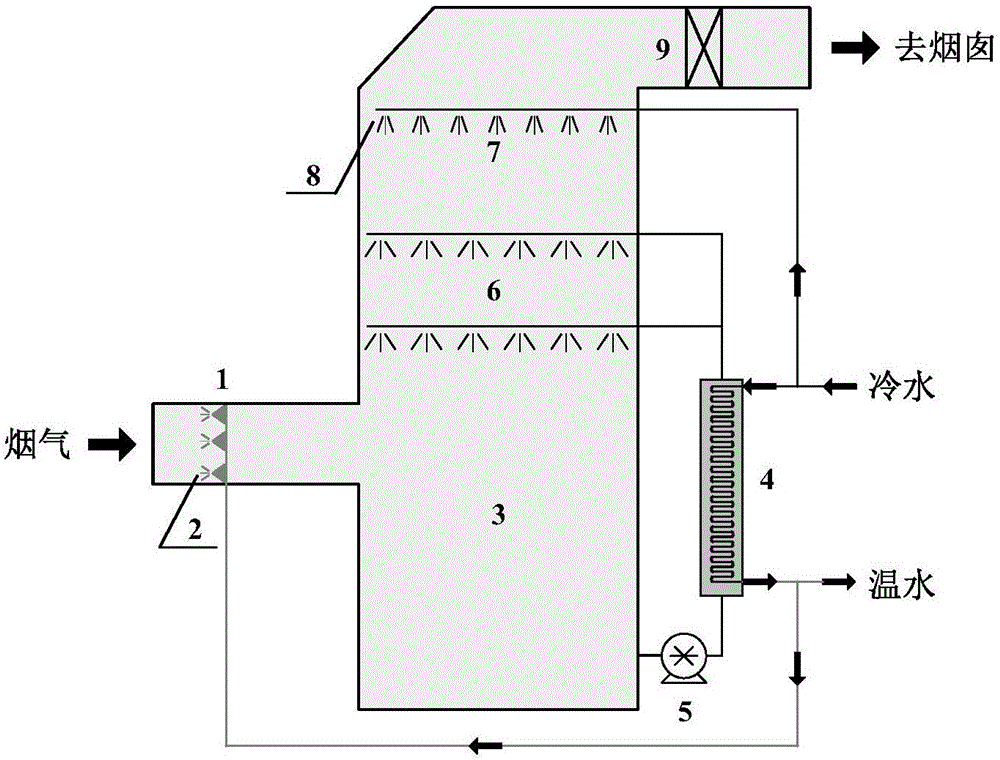
[0036] Such as figure 1 As shown, the wet desulfurization of the present invention synergistically removes fine particles and SO 3 The acid mist device mainly consists of a flue gas cooling and humidifying device 1, a desulfurization tower 3, a desulfurization scrubber heat exchanger 4, and a cold water spray layer 7 on the top of the desulfurization tower. The flue gas cooling and humidifying device 1 is installed at the inlet flue of the desulfurization tower 3, and a dual-fluid atomizing nozzle 2 is installed inside; the desulfurization scrubbing liquid heat exchanger 4 is installed on the desulfurization scrubbing liquid inlet pipe, and the heat exchanger cooling water adopts upward inlet Bottom out arrangement; the cold water spray layer 7 on the top of the desulfurization tower is set between the high-efficiency defogger 9 on the upper part of the desulfurization tower 2 and the desulfurization washing liquid spray layer 6. The distance between the cold water spray layer 7...

Embodiment 2

[0040] The flue gas is produced by a fully automatic coal-fired boiler, and the flue gas volume is 350Nm 3 / h, supplemented by aerosol generator, SO 3 The generator adds an appropriate amount of coal-fired fly ash and SO to the flue gas 3 , So that the dust concentration in coal-fired flue gas is 44mg / m 3 , Where the concentration of fine particles is 16mg / m 3 , SO 3 The concentration is 39mg / m 3 . The system consists of a flue gas cooling and humidification device, a desulfurization tower, a desulfurization scrubbing liquid heat exchanger, a desulfurization scrubbing liquid spray layer, a cold water spray layer on the top of the desulfurization tower, and a high-efficiency demister; the desulfurization tower uses limestone / gypsum flue gas Desulfurization. The desulfurization scrubber heat exchanger is a fluoroplastic heat exchanger, and the heat exchange tube diameter is 6mm fluoroplastic tube. The wet desulfurization tower adopts a spray tower with a tower diameter of 219mm a...


PUM


Abstract

The invention discloses a wet desulfurization synergized fine particle and SO3 acid mist removing method and device. The device comprises a flue gas cooling and humidifying device, a wet desulfurization tower, a desulfurization washing solution heat exchanger and a cold water spray layer at the top of the desulfurization tower. The method comprises the following steps: spraying atomized water to the inlet flue duct of the desulfurization tower for cooling and humidifying; performing heat exchange and cooling on the desulfurization washing solution; carrying out once trapping with the desulfurization washing solution when high-humidity flue gas in the desulfurization tower is over saturated in the desulfurization washing process and fine particles and SO3 acid mist are coagulated and grow up; setting a cold water spray layer between the desulfurizing liquid spray layer at the top of the tower and a high-efficient demister, and spraying and cooling with cold water to enable the flue gas to be over saturated once again, coagulating and growing the fine particles and SO3 acid mist once again, and trapping with the high-efficient demister. The method can be used for effectively reinforcing the trapping effect of a wet desulfurization system on fine particles and SO3 acid mist, the desulfurization water consumption can be reduced, and the desulfurization efficiency can be improved. The method and device are suitable for coal-fired boiler with a wet flue gas desulfurization system.

Description

[0001] 1. Technical Field [0002] The invention belongs to fine particles of coal-fired flue gas and SO 3 The technical field of acid mist emission control, in particular to an application of water vapor phase change technology to improve the wet flue gas desulfurization system for fine particulate matter and SO 3 Method and device for removing acid mist. [0003] 2. Background technology [0004] Fine particulate matter and SO 3 Acid fog pollution has become a prominent atmospheric environmental problem in my country, and it is an important factor leading to major environmental problems such as reduced atmospheric visibility, acid rain, haze weather, and global climate change. At present, more than 80% of large and medium-sized coal-fired power stations in my country adopt wet desulfurization technology. Due to the scrubbing effect of the desulfurization scrubber, the wet flue gas desulfurization system can synergistically remove some of the larger fine particles and SO in the flue...

Claims


Application Information

Patent Timeline
IPC IPC(8): B01D47/12B01D53/50B01D53/78
CPCB01D47/12B01D53/002B01D53/346B01D53/504B01D2258/0283B01D2259/124B01D2259/65
Inventor 杨林军吴昊潘丹萍张瑞
Owner SOUTHEAST UNIV
Why Eureka
Try Eureka