
Leakage hole's leakage rate measuring apparatus

A technology of leak rate measurement and leak hole, which is applied in the field of leak detection, can solve the problems of high development cost, long test cycle, and complex structure of the measurement device, and achieve the effects of wide application range, reduced measurement error, and low measurement cost

Inactive Publication Date: 2017-05-17
HEFEI UNIV OF TECH
View PDF5 Cites 3 Cited by
  • Summary
  • Abstract
  • Description
  • Claims
  • Application Information

AI Technical Summary

Problems solved by technology

When using the constant volume method to measure the leak rate of the leak hole, it needs to accumulate the gas leakage for a long time, the test cycle is relatively long, and the vacuum background effect and the change of the ambient temperature will have a great impact on the test results
In addition, when using the constant volume method to measure the leak rate of the leak hole, a standard volume vacuum chamber with high manufacturing accuracy is required to realize the accurate measurement of the volume of the constant volume chamber. The method is only suitable for measuring leaks with a large leak rate
The constant pressure method to measure the leak rate mainly uses a feedback system with high control precision to keep the gas pressure in the variable volume chamber constant. At present, the method of precision piston driving the bellows is commonly used. The structure of the measuring device is complicated and the development cost is relatively high. Compared with the constant volume method, the constant pressure method can achieve a smaller leak rate measurement, but it still cannot meet the leak rate range of most leaks.

Method used


Image

  • Leakage hole's leakage rate measuring apparatus
  • Leakage hole's leakage rate measuring apparatus

Examples


Embodiment Construction

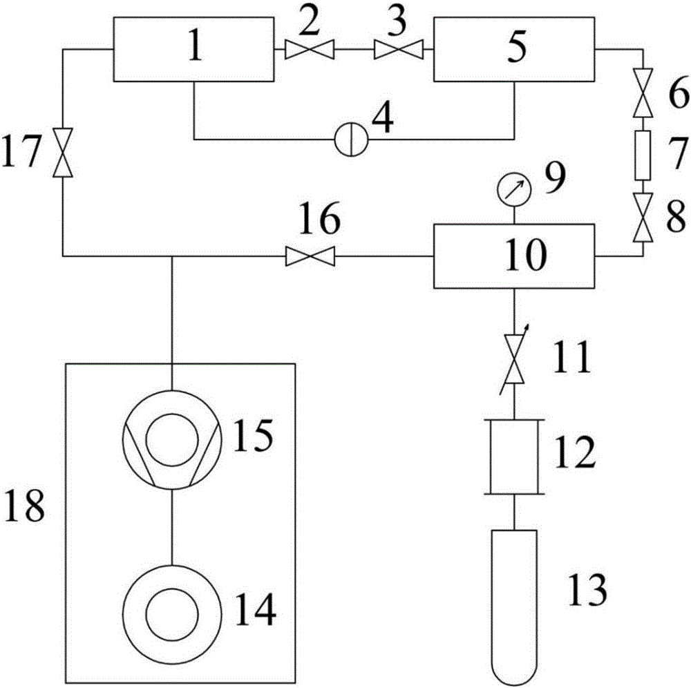
[0029] Such as figure 1 As shown, a leak rate measuring device for a leak includes a reference chamber 1, a first valve 2, a second valve 3, a differential pressure gauge 4, a measuring chamber 5, a fourth valve 6, a measuring unit 7, a fifth valve 8, an absolute Vacuum gauge 9, plenum chamber 10, needle valve 11, flow meter 12, gas cylinder 13, diaphragm pump 14, turbomolecular pump 15, sixth valve 16, third valve 17, air extraction unit 18;

[0030] The gas cylinder 13 is connected to the plenum chamber 10 through a flowmeter 12 and a needle valve 11, and an absolute vacuum gauge 9 is installed on the plenum chamber 10, and the air extraction unit 18 is connected to the plenum chamber 10 through a sixth valve 16, and is connected to the plenum chamber 10 through the sixth valve 16. The third valve 17 is connected with the reference chamber 1, the measurement unit 7 is connected with the measurement chamber 5 through the fourth valve 6, and connected with the pressure-stabili...


PUM


Abstract

The invention provides a leakage hole's leakage rate measuring apparatus which belongs to the leakage detection technology field. Through the introduction of a reference chamber completely identical to a measuring chamber with regard to the size, the materials and the processing method, it is possible to reduce the influence of background air deflation and environment temperature change on the measurement accuracy. The device is an all-metal vacuum system, comprising an all-metal valve and vacuum components such as the metal bellows. The completely metallic vacuum system is capable of reducing the errors caused by the permeation of small molecule gas so as to achieve the purpose of accurately measuring the leakage hole's leakage rate. Through the utilization of the apparatus, it is possible to realize the accurate measurement of a leakage hole's leakage rate. The leakage hole's leakage rate measuring apparatus comprises a pumping unit composed of a diaphragm pump and turbo molecular pump, an all-metal angle valve and a plug valve, an air cylinder, a flow meter, an absolute vacuum gauge, a pressure stabilizing chamber, a measuring chamber, a reference chamber, a leakage hole's leakage rate measurement unit, and a differential pressure meter. The apparatus can accurately measure the leakage hole's leakage rate and the operation process is simple and can be used for repetitive measurements.

Description

technical field [0001] The invention relates to a device for measuring the leak rate of a leak hole, which belongs to the technical field of leak detection. Background technique [0002] Leak rate detection technology is widely used in aerospace, semiconductor industry, high energy physics, nuclear industry, etc., and the requirements for accurate leak detection are getting higher and higher. For example, in the field of aerospace, the airtightness of spacecraft is an important factor affecting its on-orbit safety, so it is necessary to accurately detect its leak rate; the future semiconductor industry will develop in the direction of miniaturization and integration, and the manufacturing process The vacuum degree in the vacuum will directly affect its service life; devices in high-energy physics, nuclear industry and other fields need to work in a relatively high vacuum environment for a long time, so real-time testing of their airtightness is required. The above applicati...

Claims


Application Information

Patent Timeline
IPC IPC(8): G01M3/26
CPCG01M3/26
Inventor 王旭迪魏本猛尉伟邱克强寇钰董栋李鑫孟智鹏
Owner HEFEI UNIV OF TECH
Features
  • Generate Ideas
  • Intellectual Property
  • Life Sciences
  • Materials
  • Tech Scout
  • Unparalleled Data Quality
  • Higher Quality Content
  • 60% Fewer Hallucinations
Learn More