Clock driving method for single-ended input and differential output applied to ate test

A differential output, clock-driven technology, applied in the direction of electronic circuit testing, measuring electricity, measuring devices, etc., can solve the problems that cannot be directly provided, and achieve the effect of reducing testing cost, reducing complexity, and cheap price

Active Publication Date: 2020-02-07
SHANGHAI PRECISION METROLOGY & TEST RES INST +1
View PDF8 Cites 0 Cited by
  • Summary
  • Abstract
  • Description
  • Claims
  • Application Information

AI Technical Summary

Problems solved by technology

[0006] In order to solve the problem that MicroFLEX cannot directly provide differential digital signals as clock-driven ADC in the process of testing AD6645, the present invention further provides a circuit and method for converting single-ended digital signals directly output by MicroFLEX into differential digital signals as clock-driven

Method used


Image

  • Clock driving method for single-ended input and differential output applied to ate test
  • Clock driving method for single-ended input and differential output applied to ate test
  • Clock driving method for single-ended input and differential output applied to ate test

Examples


Embodiment Construction

[0017] The present invention is further illustrated below by way of examples.

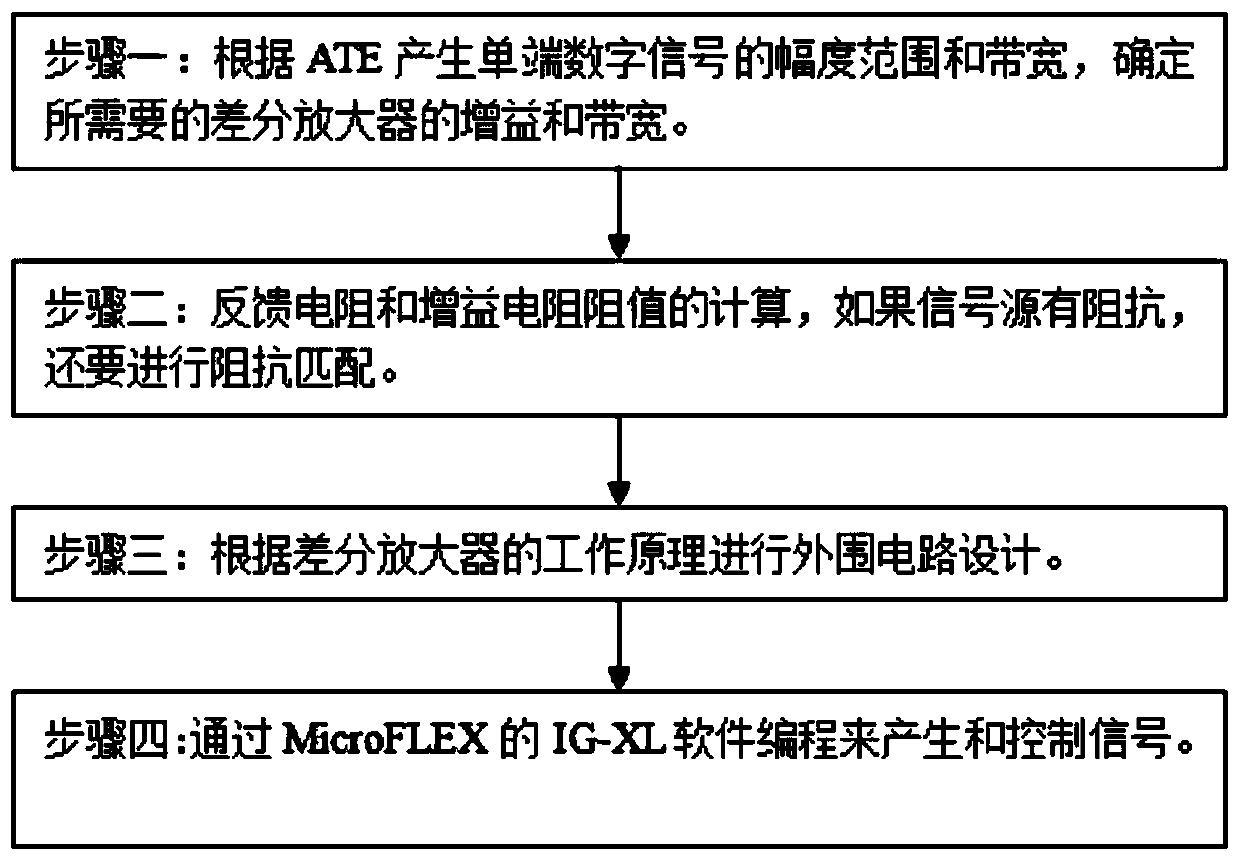
[0018] combine figure 1 , a clock driving method for single-ended input and differential output applied to ATE testing in an embodiment of the present invention includes the following steps: Step 1: Determine the required differential amplifier according to the amplitude range and bandwidth of the single-ended digital signal generated by ATE Gain and bandwidth, so as to further determine the feedback resistor value and gain resistor value of the differential amplifier.

[0019] Step 2: Calculation of the resistance value of the feedback resistor and the gain resistor. If the signal source has impedance, impedance matching must be performed.

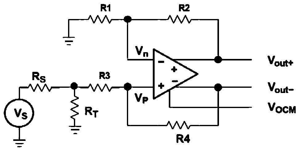
[0020] like figure 2 As shown, in the case that the signal source impedance Rs is 50Ω, equations 1 to 4 provide the calculation of the resistance value of the fully differential amplifier, in order to obtain the balance equation.

[0021]

[0022]

...


PUM


Abstract

The invention relates to a clock driving method for the single-ended input differential output of ATE testing. According to the method, a differential amplifier THS4503 and peripheral circuits thereof are adopted to convert single-ended digital signals generated by a MicroFLEX into differential digital signals required by an AD6645. The method includes the following steps that: the gain and bandwidth of a required differential amplifier are determined according to the amplitude range and bandwidth of single-ended digital signals generated by ATE; step 2, the values of feedback resistance and gain resistance are calculated, if a signal source has impedance, impedance matching is performed; step 3, peripheral circuit design is performed according to the working principle of the differential amplifier; and step 4, signals are generated and controlled through the IG-XL software programming of the MicroFLEX.

Description

technical field [0001] The invention relates to the field of integrated circuit testing, in particular to a clock drive circuit for single-end digital signal input and differential digital signal output involved in testing a high-speed and high-precision analog-to-digital converter (ADC) AD6645 using an automatic test equipment (ATE) MicroFLEX. Background technique [0002] The differential signal has the advantages of strong anti-interference ability, effective suppression of electromagnetic interference, and accurate timing positioning. The differential digital signal is not easy to make mistakes and can avoid retransmissions caused by verification errors. In this sense, the transmission rate of differential signals is higher, so many The clock signal of the ADC uses a pair of differential signals. When the input is a single-ended signal, it is necessary to use a single-ended to differential circuit to convert the single-ended signal into a differential signal, and then inp...

Claims


Application Information

Patent Timeline
Patent Type & Authority Patents(China)
IPC IPC(8): G01R31/28H03M3/02
CPCG01R31/2851H03M3/02
Inventor 刘伟徐导进许伟达潘潇雨
Owner SHANGHAI PRECISION METROLOGY & TEST RES INST
Why Eureka
Try Eureka