Optical capturing and detecting device and method based on quantum photon nano-jet array

A photonic nanometer and optical trapping technology, which is applied in the optical field to achieve high-efficiency optical trapping and detection, flexible operation, and simple device structure.

Inactive Publication Date: 2017-05-17
JINAN UNIVERSITY
View PDF7 Cites 15 Cited by
  • Summary
  • Abstract
  • Description
  • Claims
  • Application Information

AI Technical Summary

Problems solved by technology

[0004] In order to achieve the above object, the present invention provides a device and method for optical capture and detection based on photon nanojet array, which solves the problem t

Method used


Image

  • Optical capturing and detecting device and method based on quantum photon nano-jet array
  • Optical capturing and detecting device and method based on quantum photon nano-jet array
  • Optical capturing and detecting device and method based on quantum photon nano-jet array

Examples


preparation example Construction

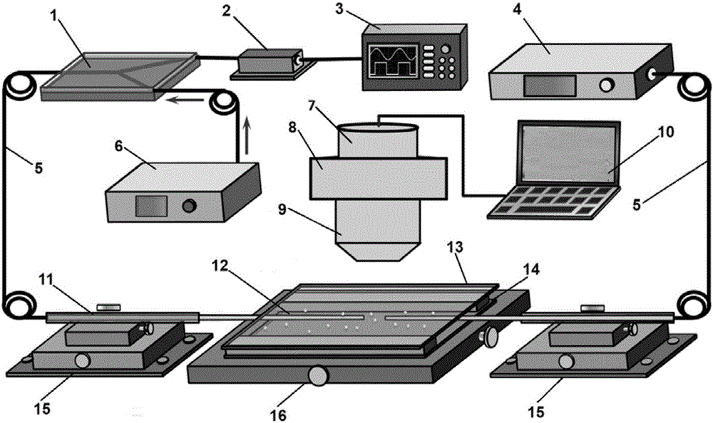
[0066] The specific preparation method is as follows: After stripping a 2 cm coating layer in the middle of the optical fiber with an optical fiber stripper, insert it into a glass capillary to protect the optical fiber. The inner diameter of the capillary is 0.9 mm and the wall thickness is 0.1 mm. , with a length of 12 cm, and then place the bare optical fiber parallel to the outer flame above the alcohol lamp, let it stand for about 40 seconds until the optical fiber is melted, and draw the molten part with the help of hands at a speed of 2 mm per second. The fiber is 45 microns long and about 1.6 mm in length. Then take the fiber away from the flame, let it stand at room temperature for 2 minutes, and finally cut off the thinned part with a fiber cutter.

[0067] The diameter of the fiber optic probe can be adjusted by the speed of drawing and the position of cutting.

[0068] Step 2: Make Microlens Array

[0069] Using photophoretic technology, a regular two-dimensional ...

Embodiment

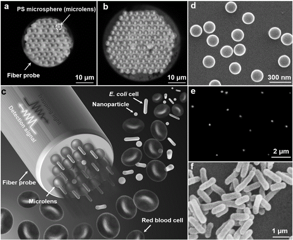
[0079] The microlens used in this embodiment is a polystyrene microsphere with a diameter of 3 microns, which has a high refractive index and low optical absorption, and is easy to generate photon nanojet.

[0080] like figure 2 As shown in (a), 60 microlenses are assembled on a fiber optic probe with a diameter of 28 μm.

[0081] With larger diameter fiber optic probes, it is possible to assemble a larger range of microlens arrays, such as figure 2 As shown in (b), 130 microlenses were assembled on a fiber optic probe with a diameter of 45 μm.

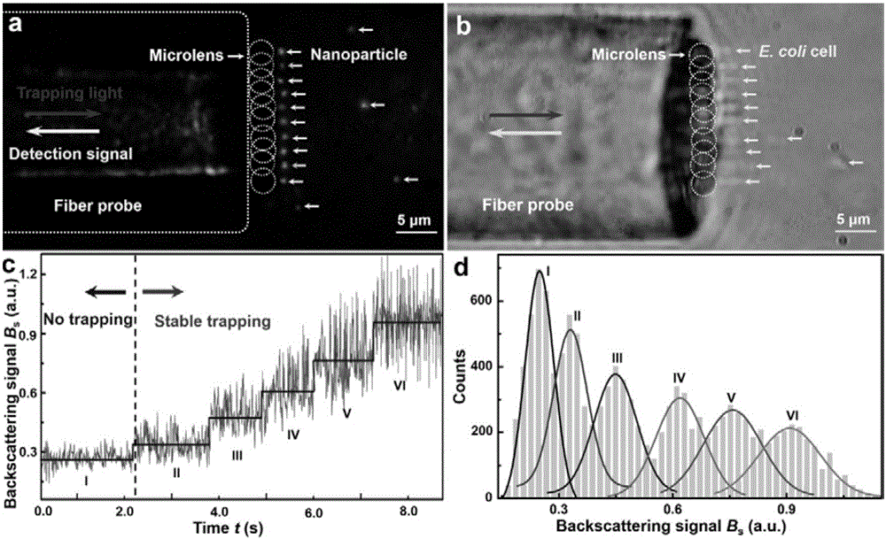
[0082] When the laser light passes through the fiber optic probe, each microlens will strongly converge the light, and behind the microlens will generate bundles of parallel sub-wavelength beams, called nanojet arrays, which can be used for capture and detection Nanoparticles and subwavelength cells, such as figure 2 (c) The schematic diagram shows that multiple nanoparticles and E. coli cells in the blood are selectively trappe...


PUM

PropertyMeasurementUnit
Diameteraaaaaaaaaa
Diameteraaaaaaaaaa
Diameteraaaaaaaaaa

Abstract

The invention discloses a device of optical capturing and detecting based on quantum photon Nano-jet array. The device comprises a microscope, a microfluidic channel is arranged on an microscopic objective table, the microfluidic channel consists of a cover glass and a glass slide, two optical fibers are placed inside the microfluidic channel, two optical fibers are respectively sleeved a glass capillary, the glass capillary is fixed on an adjustable light regulation frame, wherein end of one optical fiber is connected with a Y-tape optical fiber coupler,a photoelectric detector and a fiber laser, other end of the photoelectric detector is connected with an oscilloscope, other end of the other optical fiber is connected with a laser device. The invention further discloses a method of optical capturing and detecting based on quantum photon Nano-jet array, comprises the following steps: 1, preparing a mini-type optical fiber probe for capturing and detecting; 2, making a micro-lens array; 3, using the assemble micro-lens for capturing and detecting fluorescence Nano-particles; 4, using the assemble micro-lens for capturing and detecting colon bacillus.

Description

technical field [0001] The invention belongs to the field of optical technology, and relates to an optical capture and detection device and method based on a photon nano-jet array. Background technique [0002] Traditional optical tweezers can effectively capture and detect micron-scale particles, but due to the diffraction limit, it is difficult to act on nano-scale particles, especially it is impossible to capture and detect nanoparticles with high selectivity, high efficiency and high precision. and subwavelength cells. [0003] Plasmonic optical tweezers and photonic crystal resonators use nanoantennas and photonic crystal arrays to selectively and efficiently capture and detect nanoparticles, but they are prone to thermal effects, causing irreversible light to nanoparticles, especially biological cells. damage, moreover, these methods require complex nanostructures and precise nanofabrication processes. Contents of the invention [0004] In order to achieve the abov...

Claims


Application Information

Patent Timeline
IPC IPC(8): G02B21/32G01N15/10
CPCG01N15/10G01N2015/1006G02B21/32
Inventor 李宝军雷宏香李宇超张垚
Owner JINAN UNIVERSITY
Why Eureka
Try Eureka