


Quick Research
Generate reliable direction feasibility study reports for your R&D in just a few steps.

Technical Q&A
Discover and master advanced knowledge NOW. Basics, ideas, possibilities, all at once.

Find Solutions
As an expert in R&D theories, this can generate solutions to your technical problems instantly.

Evaluate Feasibility
Analyze your overall solution with one click, know your potential R&D risks in advance.

Monitor Landscape
Get weekly tech updates, stay abreast of the latest tech innovations and key insights.
Micromixer for fluid materials
A fluid material, micro-mixing technology, applied in mixers, chemical instruments and methods, chemical/physical processes, etc., can solve the problems of difficulty in manufacturing large-scale micro-mixing equipment and high equipment production costs, saving raw materials and reducing equipment bulk density. , the effect of high mixing efficiency
- Summary
- Abstract
- Description
- Claims
- Application Information
AI Technical Summary
Problems solved by technology
Method used
Image

Examples
specific Embodiment 1
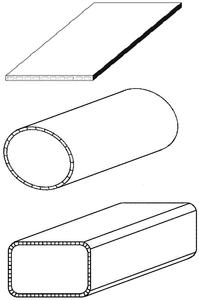
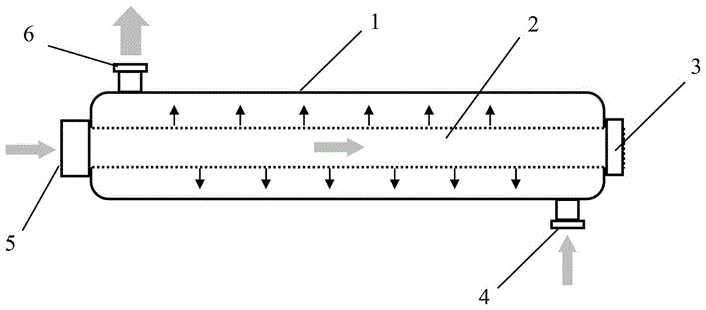
[0035] A micro-hybrid device based on a planar multi-channel ceramic element with a structure such as figure 2 shown.
[0036] Wherein, the flat multi-channel ceramic element is a porous alumina material. The manufacturing steps of the ceramic element are as follows:
[0037] 1. Mix 4 kg of alumina powder with a median particle size of 20 μm and 0.2 kg of firing aids evenly;
[0038] 2. Add 300 g of methyl cellulose, 150 g of glycerin, 15 g of oleic acid, 150 g of vacuum mineral oil and 900 g of water, and through the steps of mixing, mud refining, aging, etc., to obtain plastic mud;
[0039] 3. Use an extruder to extrude the mud into a flat multi-channel green body;
[0040] 4. The green body is dried by microwave radiation;
[0041]5. The dried green body is heated up to 400°C at a speed of 2°C / min and kept for 1 hour, and then heated to 1400°C at a speed of 2°C / min for 2 hours, and then cooled with the furnace.
[0042] After the fired ceramic product is cut, it is ob...
specific Embodiment 2
[0047] A micro-mixing device based on a flat multi-channel ceramic element, the basic structure of which is similar to the specific example 1, except that the micro-mixing device includes 10 ceramic elements 2 arranged in parallel. By increasing the number of ceramic elements 2, the material handling capacity of the micro-mixing device can be conveniently increased.
specific Embodiment 3
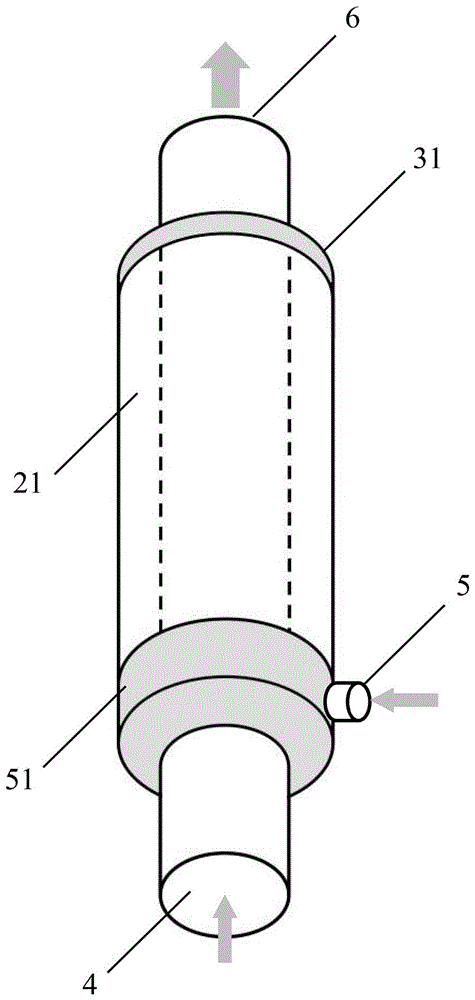
[0049] A micro-hybrid device based on a cylindrical multi-channel ceramic element, the basic structure of which is image 3 shown.
[0050] Wherein, the cylindrical multi-channel ceramic element is a porous silicon carbide material. The manufacturing steps of the ceramic element are as follows:
[0051] 1. Mix 4.5 kg of black silicon carbide powder with a median particle size of 12 μm, 0.3 kg of kaolin with a median particle size of 0.5 μm, and 0.2 kg of alumina powder with a median particle size of 0.5 μm;
[0052] 2. Add 300 g of hydroxypropyl methylcellulose, 120 g of glycerin, 15 g of oleic acid, 120 g of vacuum mineral oil and 850 g of water, and through the steps of mixing, mud refining, aging, etc., to obtain plastic mud;
[0053] 3. Use an extruder to extrude the mud into a circular multi-channel green body;
[0054] 4. After drying the green body at room temperature for 24 hours, put it in an oven at 80°C for 8 hours;
[0055] 5. The dried green body is heated up ...
PUM
| Property | Measurement | Unit |
|---|---|---|
| Thickness | aaaaa | aaaaa |
| Pore size | aaaaa | aaaaa |
| Particle size | aaaaa | aaaaa |
Abstract
Description
Claims
Application Information
 - R&D Engineer
- R&D Manager
- IP Professional
- Industry Leading Data Capabilities
- Powerful AI technology
- Patent DNA Extraction
Browse by: Latest US Patents, China's latest patents, Technical Efficacy Thesaurus, Application Domain, Technology Topic, Popular Technical Reports.
© 2024 PatSnap. All rights reserved.Legal|Privacy policy|Modern Slavery Act Transparency Statement|Sitemap|About US| Contact US: help@patsnap.com