Low-quality waste heat recovery power generation device

A technology of waste heat recovery and power generation device, which is applied in steam generation devices, steam engine devices, steam generation and other directions, can solve the problems of limited utilization of low-quality waste heat, large floor space and high cost, and avoid inconvenient acquisition and energy utilization. High, simple structure

Inactive Publication Date: 2017-05-31
HEBEI UNIV OF TECH
View PDF5 Cites 5 Cited by
  • Summary
  • Abstract
  • Description
  • Claims
  • Application Information

AI Technical Summary

Problems solved by technology

Semiconductor thermoelectric power generation technology refers to the conversion of waste heat energy into electrical energy through intermediate heat transfer media such as semiconductors. This power generation technology has the advantages of simple structure, convenient use, safety and pollution-free, etc., but due to high cost and other reasons, this technology is limited to applications in Some advanced fields such as military and aerospace
In steam turbine power generation technology and screw power generation technology, the energy saving and economic benefits of using waste heat power generation are considerable, and it has good promotion and utilization value, but it requires a lot of supporting systems and equipment, covers a large area, and costs high
In addition, due to the high steam demand of the steam turbine and the screw power machine, when the steam source is insufficient, it is impossible to drive the ultra-high-power steam generator set
However, in Roots-type steam power generation technology, steam from low-quality waste heat is mainly used, and the flue gas content in industry is relatively large, so the use of low-quality waste heat other than steam is relatively limited.

Method used


Image

  • Low-quality waste heat recovery power generation device
  • Low-quality waste heat recovery power generation device
  • Low-quality waste heat recovery power generation device

Examples


Embodiment Construction

[0017] Specific examples of the present invention are given below. The specific embodiments are only used to further describe the present invention in detail, and do not limit the protection scope of the claims of the present application.

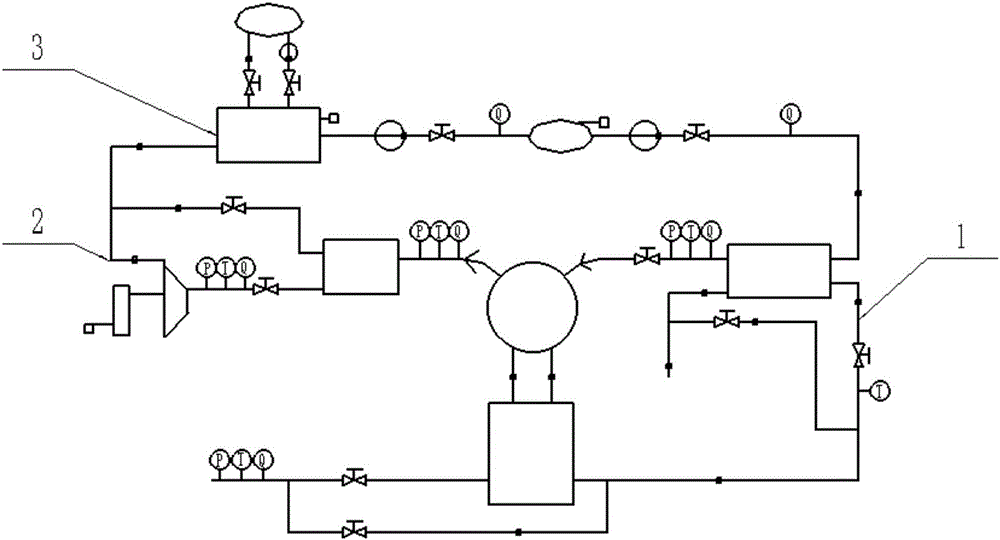
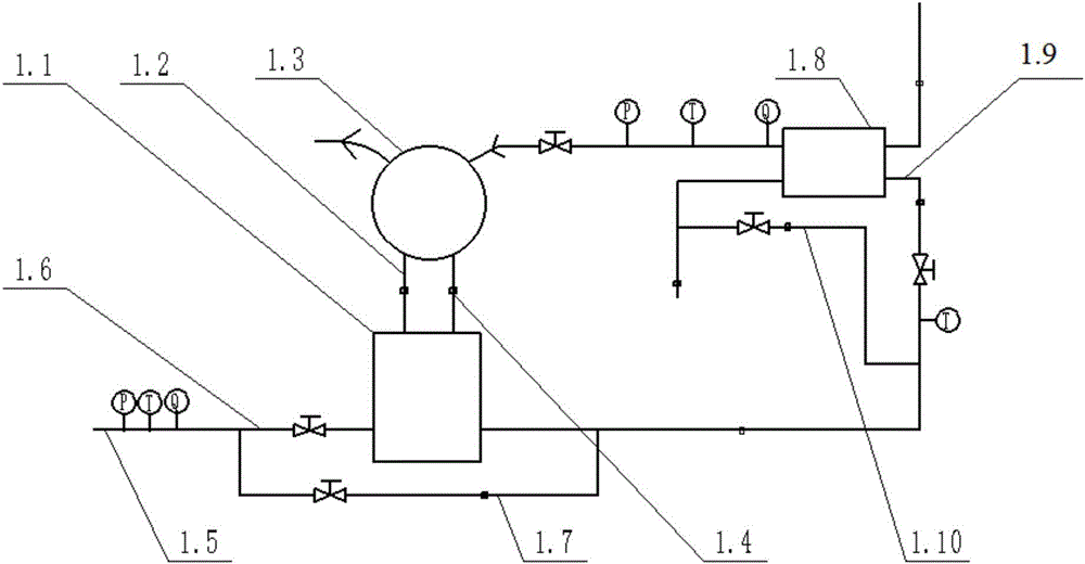
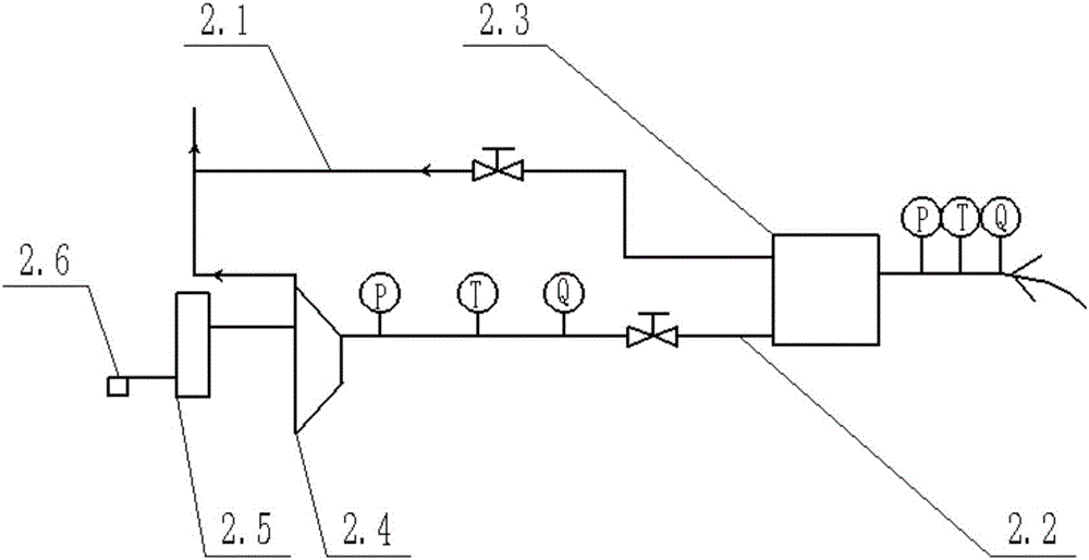
[0018] The present invention provides a low-quality waste heat recovery power generation device (see Figure 1-4 , device for short); including resource recovery system 1, power generation system 2 and water supply system 3; said resource recovery system 1 includes heat pipe steam generator 1.1, descending steam pipeline 1.2, steam drum 1.3, rising steam pipeline 1.4, flue gas Inlet 1.5, flue gas main road 1.6, flue gas bypass 1.7, economizer 1.8, economizer flue gas pipeline 1.9 and excess flue gas discharge pipeline 1.10; the power generation system 2 includes steam bypass 2.1, steam Main road 2.2, gas storage tank 2.3, Roots type power machine 2.4, generator 2.5 and power quality monitor 2.6; the water supply system 3 includes condenser...


PUM


Abstract

The invention discloses a low-quality waste heat recovery power generation device. The low-quality waste heat recovery power generation device comprises a resource recovery system, a power generation system and a water supply system; the resource recovery system comprises a heat tube steam generator, a descending steam pipeline, a steam manifold, an ascending steam pipeline, a flue gas inlet, a flue gas primary path, a flue gas bypass, a coal saver, a flue gas pipeline entering the coal saver and a residual flue gas exhaust pipeline; the power generation system comprises a steam bypass, a steam primary path, a gas storage tank, a root's power machine, a power generator and an electric energy quality monitoring instrument; the water supply system comprises a condenser, a deaerator, a drainage pipeline, a water supply tank, a condensing and supplementing pump, a condenser liquidometer, a water supply pipeline, a condensing pump, a water feeding pump and a deaerator liquidometer. A circulating work medium in the device is water and steam which circulate, a flue gas in a low-quality waste heat resource can be recycled. The device is simple in structure, low in cost and high in utilization ratio of energy sources.

Description

technical field [0001] The invention relates to an industrial waste heat recovery power generation device, in particular to a low-quality waste heat recovery power generation device. Background technique [0002] The generation of industrial waste heat energy is due to the consumption of coal, oil and various combustible gas emissions in the process of industrial production, which belongs to secondary energy. With the increase of fuel consumption such as coal and petroleum, the emission of industrial waste heat energy is bound to increase significantly. If the potential energy contained in it is not recycled, it will cause a huge waste of energy. Nowadays, waste heat power generation technologies that have been industrialized in various industries are: coke oven tail gas waste heat recovery power generation technology used in the coking industry, CDQ power generation technology used in the steel industry, blast furnace top pressure, converter, sintering and heating furnace ...

Claims


Application Information

Patent Timeline
Patent Type & Authority Applications(China)
IPC IPC(8): F22B35/00F01K27/02F22B33/00
CPCF01K27/02F22B33/00F22B35/00F22B35/001Y02P80/15
Inventor 肖艳军朱娜肖艳春张宗华
Owner HEBEI UNIV OF TECH
Why Eureka
Try Eureka