
Waveguide broadband detector

A geophone and waveguide technology, applied in the direction of electromagnetic field characteristics, etc., can solve the problems of large loss of microstrip line, increased dispersion effect, crushed substrate, etc. Effect

Inactive Publication Date: 2017-05-31
THE 41ST INST OF CHINA ELECTRONICS TECH GRP
View PDF4 Cites 5 Cited by
  • Summary
  • Abstract
  • Description
  • Claims
  • Application Information

AI Technical Summary

Problems solved by technology

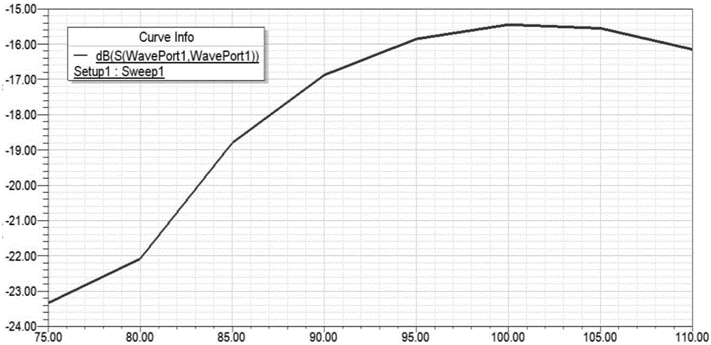
[0007] The probe conversion from waveguide to microstrip is an important factor affecting the bandwidth of the waveguide detector. It is difficult to achieve a good return loss in the whole waveguide frequency band. Taking 3mm as an example, the optimized simulation results are as follows figure 2 It can be seen from the figure that the return loss is better than 15dB, and the full waveguide bandwidth characteristics are not very ideal. At the same time, the waveguide probe needs to be inserted into the waveguide without supporting parts, so a hard substrate is used. The installation and fixation of the cavity has high requirements for machining accuracy and assembly technology, otherwise it is very easy to crack or crush the substrate, causing the detection circuit to fail
[0008] The detection diode is installed on the microstrip line. It is difficult to match the size of the diode pin and the microstrip line. The conductive glue or solder used in the assembly is likely to bring additional parasitic parameters in the millimeter wave frequency band, which makes broadband matching difficult and deteriorates The frequency response of the detector; at the same time, the dispersion effect of the microstrip line in the millimeter wave frequency band increases significantly, and the loss is large, which will cause the power loss of the millimeter wave signal and reduce the detection efficiency of the detector
[0009] Therefore, the disadvantages of the prior art are: (1) the hard substrate waveguide probe coupling technology is adopted, the bandwidth is not wide enough, and the detection performance of the full waveguide bandwidth is relatively poor; (2) broadband matching and circuit assembly are relatively difficult, and the frequency response is relatively poor; (3) The microstrip line has a large loss in the millimeter wave frequency band, and the detector sensitivity is relatively low

Method used


Image

  • Waveguide broadband detector
  • Waveguide broadband detector
  • Waveguide broadband detector

Examples


Embodiment Construction

[0033] The specific embodiment of the present invention will be further described below in conjunction with accompanying drawing and specific embodiment:

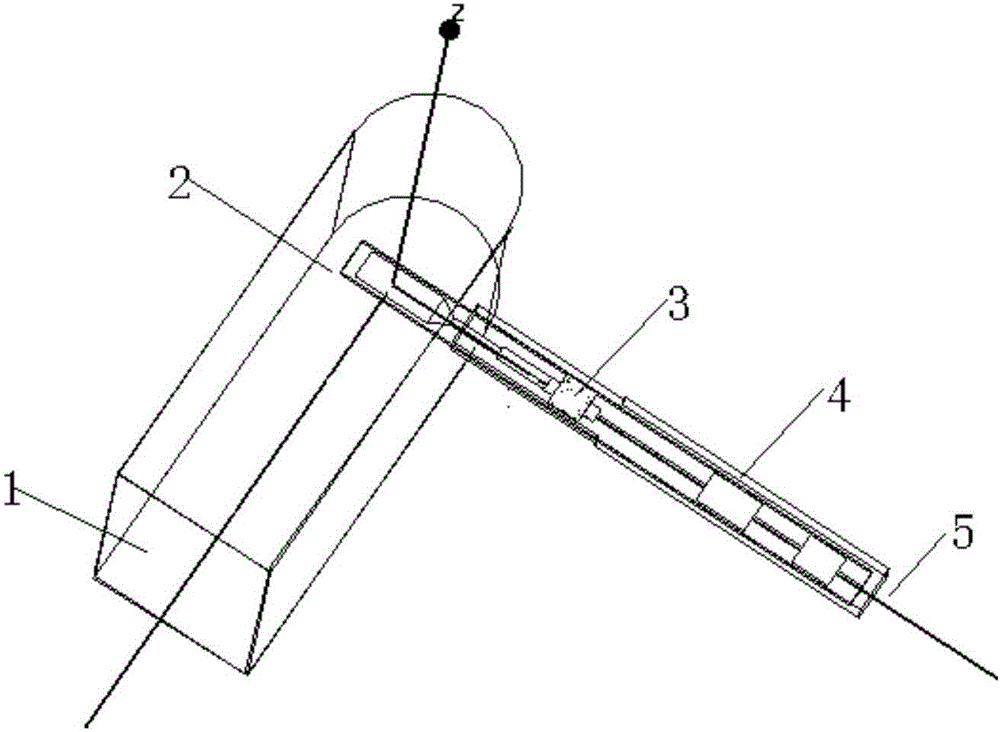
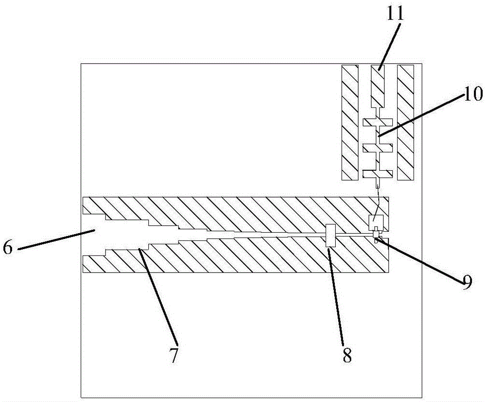
[0034] Such as Figure 3-5 As shown, a waveguide broadband detector includes a waveguide and a detector circuit arranged in the waveguide, the detector circuit includes a fin line broadband conversion circuit, the fin line broadband conversion circuit is provided with a fin line, and the end of the fin line is provided with a diode 9, The front end of the diode 9 contacts the edge of the waveguide through a metal fin to form a DC ground loop, and the distance to the diode 9 is a quarter wavelength of the detection input signal 6. A signal reflection circuit 8 is provided.

[0035] The detection circuit is arranged on the dielectric substrate 15, and the dielectric substrate 15 is a soft dielectric substrate.

[0036] The waveguide is a rectangular waveguide, including a butt joint upper half 12 and a lower half 13 , and a ...


PUM


Abstract

The invention discloses a waveguide broadband detector, and specifically relates to the technical field of millimeter wave waveguide detection. The invention irons out the defects that a conventional detector is not sufficient in bandwidth, is poorer in detection performance of full waveguide bandwidth, is larger in loss of a microstrip line at a millimeter wave band, is relatively low in sensitivity, is relatively difficult for diode bandwidth matching and detection circuit assembly and is poorer in frequency response because the conventional detector employs the technology of hard substrate waveguide probe coupling. The detector comprises a waveguide and a detection circuit disposed in the waveguide. The detection circuit comprises a fin line broadband conversion circuit, and the fin line broadband conversion circuit is provided with a fin line. The tail end of the fin line is provided with a diode, and the front end of the diode makes contact with the edge of the waveguide through a metal fin, thereby forming a DC grounding loop. A signal reflection circuit is disposed at a part, with the distance to the diode being a quarter of the wavelength of a detection input signal.

Description

technical field [0001] The invention relates to the technical field of millimeter wave waveguide detection, in particular to a waveguide broadband detector. Background technique [0002] The detector is one of the conventional components in microwave and millimeter wave technology, which can complete the functions of microwave and millimeter wave signal detection, automatic gain control, power detection, etc., and is widely used in signal sources, vector network analyzers, microwave instantaneous receivers, microwave remote sensing It plays a very important role in the whole system such as the probe. Due to the small signal power in the millimeter wave frequency band, higher requirements are put forward for performance indicators such as the sensitivity, standing wave ratio, operating bandwidth, and dynamic range of the detector. Various applications urgently need to provide a broadband in the millimeter wave band. High efficiency broadband detector with good frequency resp...

Claims


Application Information

Patent Timeline
IPC IPC(8): G01R29/08
CPCG01R29/08
Inventor 赵爱英范国清张文兴李鸽
Owner THE 41ST INST OF CHINA ELECTRONICS TECH GRP
Learn More