Spherical opposite-spraying type batched nanofiber yarn processing device and using method thereof

A nanofiber and processing device technology, which is applied in the direction of yarn, spinning machine, spinneret assembly, etc., can solve the problem of uncontrollable nanofiber yarn structure, low production speed of nanofiber yarn, and easy breakage of nanofiber yarn First-class problems, achieve the effect of improving spinning quality, convenient operation, and avoiding concentration fluctuations

Active Publication Date: 2017-06-09
DONGHUA UNIV
View PDF8 Cites 7 Cited by
  • Summary
  • Abstract
  • Description
  • Claims
  • Application Information

AI Technical Summary

Problems solved by technology

[0008] The technical problem to be solved by the present invention is to provide a spherical pair spraying type batch nanofiber yarn processing device and its use method, which solves the problems of low production speed of nanofiber yarn, uncontrollable structure of nanofiber yarn, nanofiber yarn Problems such as low strength of fiber yarn, easy breakage of nanofiber yarn and difficulty in continuous production

Method used


Image

  • Spherical opposite-spraying type batched nanofiber yarn processing device and using method thereof
  • Spherical opposite-spraying type batched nanofiber yarn processing device and using method thereof
  • Spherical opposite-spraying type batched nanofiber yarn processing device and using method thereof

Examples


Embodiment 1

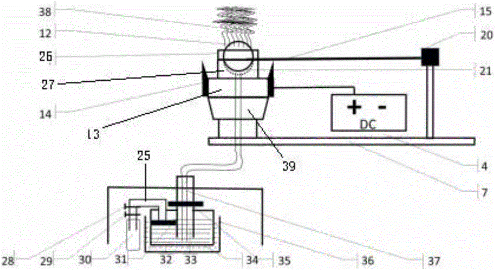
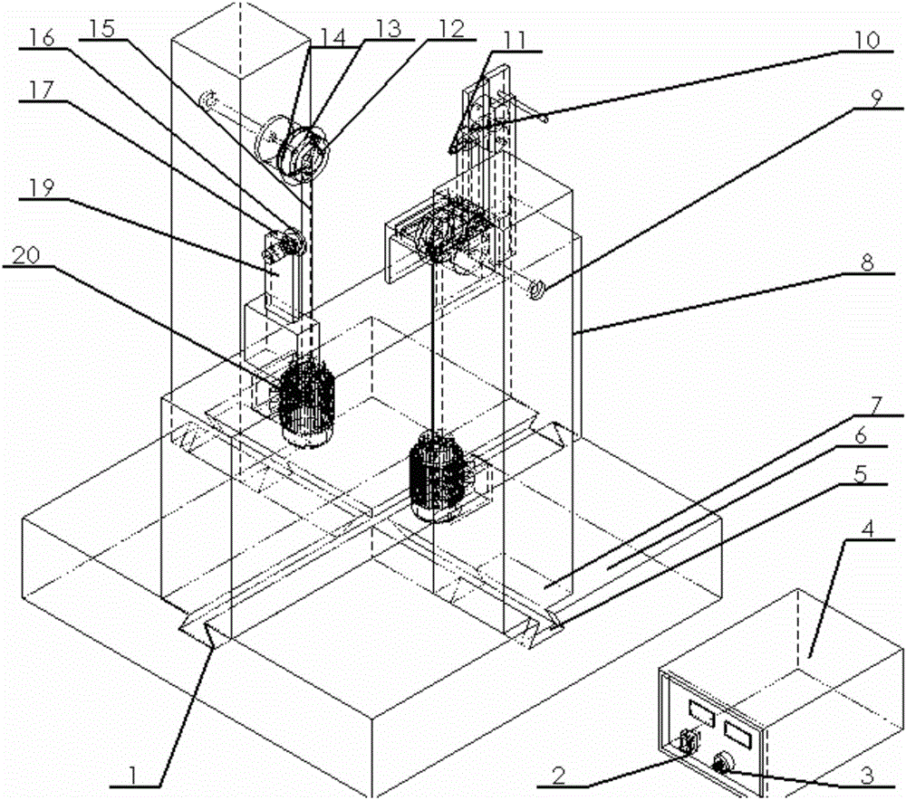
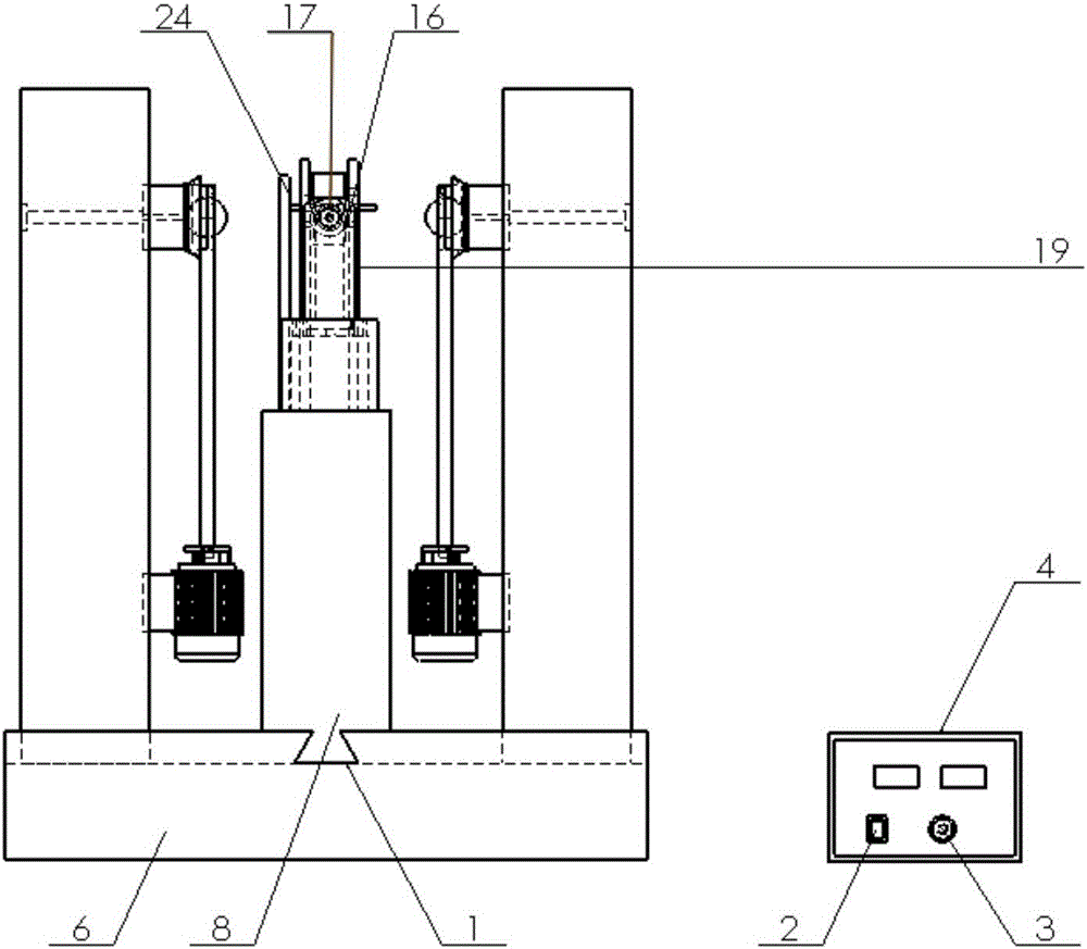
[0046] Such as Figure 1 to Figure 5 As shown, a ball-to-brush batch nanofiber yarn processing device includes a body 23 and a base 6, wherein the base 6 is provided with cross wedge-shaped grooves 1 and 5 in the middle, and the body 23 is along the first A wedge-shaped groove 1 is symmetrically arranged on the second wedge-shaped groove 5, and the body 23 includes a liquid supply system, a separation electric field control system, a spherical brush-type spinning system, a nanofiber yarn forming system and a nanofiber yarn collection system, The liquid supply system includes a gas cylinder 30, a spinning solution storage bottle 34, an oil bath 36 and a catheter 37, the spinning solution storage bottle 30 is arranged in the oil bath 36, and the spinning solution storage The liquid bottle 30 and the liquid guide tube 37 form a connector structure to the brush liquid tank 21. The spinning liquid storage bottle 34 is connected to the gas cylinder 30 through the gas pipe 25. On the...

Embodiment 2

[0075] Next, nanofibers are prepared by using a polymer solution prepared from polyacrylonitrile (PAN) and N-N dimethylformamide (DMF). The mass fraction of the prepared PAN polymer solution is 10%. Inject the configured PAN / DMF high polymer solution into the liquid storage bottle 34, and connect the liquid storage bottle 34 and the brush liquid tank 21 through the liquid supply channel 9 with the catheter 37; The position of the second wedge-shaped groove 5 on the nanometer yarn device base 6 of the mount 7 of the silk device 23 makes the distance between the two mounts 20cm; adjust the height of the metal ring 14 of the two spherical spinning devices on the cylinder seat 13 respectively The distance between the top and the top of the spherical nozzle 12 is 40mm; adjust the position of the yarn-forming seat 8 on the first wedge-shaped groove 1 on the base 6 of the nano-yarn device; adjust the height of the metal disc seat 19, and adjust the position of the yarn-drawing hole s...

Embodiment 3

[0077] Next, nanofibers are prepared by using a polymer solution prepared from polyacrylonitrile (PAN) and N-N dimethylformamide (DMF). The mass fraction of the prepared PAN polymer solution is 12%. Inject the configured PAN / DMF high polymer solution into the liquid storage bottle 34, and connect the liquid storage bottle 34 and the brush liquid tank 21 through the liquid supply channel 9 with the catheter 37; The position of the second wedge-shaped groove 5 on the nanometer yarn device base 6 of the mount 7 of the silk device 23 makes the distance between the two mounts 20cm; adjust the height of the metal ring 14 of the two spherical spinning devices on the cylinder seat 13 respectively The distance between the top and the top of the spherical nozzle 12 is 40mm; adjust the position of the yarn-forming seat 8 on the first wedge-shaped groove 1 on the base 6 of the nano-yarn device; adjust the height of the metal disc seat 19, and adjust the position of the yarn-drawing hole s...


PUM

PropertyMeasurementUnit
diameteraaaaaaaaaa
lengthaaaaaaaaaa
diameteraaaaaaaaaa

Abstract

The invention relates to a spherical opposite-spraying type batched nanofiber yarn processing device and a using method thereof. The device comprises a body and a base. Crossed wedge grooves are formed in the middle of the base. The body is symmetrically arranged on the second wedge groove along the first wedge groove. The body comprises a liquid supply system, a separation electric field control system, a spherical brush type spinneret system, a nanofiber yarn forming system and a nanofiber yarn collecting system. The liquid supply system comprises an air cylinder, a spinning solution storage bottle, an oil bath groove and a liquid guiding pipe. The spinning solution storage bottle is arranged inside the oil bath groove. The spinning solution storage bottle, the liquid guiding pipe and a liquid brushing groove form a communicating vessel structure. The spinning solution storage bottle is connected with the air cylinder through an air pipe. A main valve and a pressure reduction valve are sequentially arranged at the portion, close to the air cylinder, of the air pipe. Due to the liquid supply system adopting the air pressure communicating vessel, automatic supply of a high polymer solution can be achieved, and the device is simple and easy to use, and convenient to operate.

Description

technical field [0001] The invention belongs to the technical field of nanometer electrospinning and textile machinery, and in particular relates to a spherical pair-brush type batch nanofiber yarn processing device and a method for using the same. Background technique [0002] When polymer fiber diameters are reduced from the micrometer scale to the submicrometer or nanometer scale, a surprising set of properties emerges. Such as a very large volume specific surface area, the volume specific surface area of ​​nanofibers is basically 1000 times that of microfibers; it can be flexibly functionalized on the surface; it shows superior effects and mechanical properties compared with other known material forms, such as surface And interface effect, small size effect, quantum size effect and quantum tunneling effect and stiffness, tensile strength, etc. These outstanding properties make nanofibers the material of choice for many important applications, and have great development ...

Claims


Application Information

Patent Timeline
Patent Type & Authority Applications(China)
IPC IPC(8): D02G3/02D01D1/06D01D4/02D01D7/00D01H4/04
CPCD01D1/06D01D4/02D01D7/00D01H4/04D02G3/02
Inventor 覃小红熊健
Owner DONGHUA UNIV
Why Eureka
Try Eureka