LED light source used for aquiculture

An LED light source and aquaculture technology, applied in the field of optoelectronics, can solve the problems of the light source not being suitable for green environmental protection, energy saving and emission reduction, etc., and achieve the effect of convenient light source ratio and photoperiod, small absorption coefficient, and regulation of light source ratio and photoperiod

Inactive Publication Date: 2017-06-13
UNIV OF ELECTRONICS SCI & TECH OF CHINA
View PDF12 Cites 8 Cited by
  • Summary
  • Abstract
  • Description
  • Claims
  • Application Information

AI Technical Summary

Problems solved by technology

Therefore, the traditional gas discharge light source is no longer suitable for environmental protection, energy saving and emission reduction, and the requirements of optimizing light environment parameters.

Method used


Image

  • LED light source used for aquiculture
  • LED light source used for aquiculture
  • LED light source used for aquiculture

Examples


Embodiment 1

[0037] Weigh the green fluorescent powder and powder mixing glue according to the ratio of 1:6 and mix them evenly, vacuumize the mixed slurry with a vacuum degassing machine, and obtain the fluorescent powder slurry after removing air bubbles;

[0038] Clean the surface of the blue LED chip with a plasma cleaning machine, apply the phosphor powder slurry directly on the surface of the LED chip by dispensing, put it in a drying oven and heat (150°C) for 2 hours to obtain a cured phosphor layer;

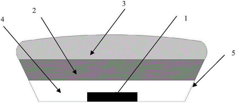
[0039] Then use the glue dispensing method to evenly coat a specific shape of silica gel on the phosphor layer as a light-transmitting layer, and then heat (120°C) in a drying oven to cure for 2 hours to obtain a light-transmitting layer;

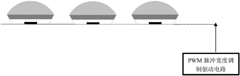
[0040] Finally, the light intensity of a group of LED chips is adjusted through the PWM pulse width modulation driving circuit.

Embodiment 2

[0042] Weigh the green fluorescent powder and powder mixing glue according to the ratio of 1:6 and mix them evenly, vacuumize the mixed slurry with a vacuum degassing machine, and obtain the fluorescent powder slurry after removing air bubbles;

[0043] Clean the surface of the blue LED chip with a plasma cleaning machine, apply the phosphor powder slurry directly on the surface of the LED chip by dispensing, put it in a drying oven and heat (150°C) for 2 hours to obtain a cured phosphor layer;

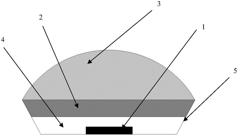
[0044] Cover the above-mentioned LED chip with a hemispherical lens cap, pour silica gel into the inside, and then heat (120°C) in a drying oven for 2 hours to obtain a light-transmitting layer;

[0045] The resulting LED chip structure is as figure 1 As shown, the light intensity of a group of LED chips is adjusted through the PWM pulse width modulation driving circuit.

Embodiment 3

[0047] Weigh the green fluorescent powder and powder mixing glue according to the ratio of 1:6 and mix them evenly, vacuumize the mixed slurry with a vacuum degassing machine, and obtain the fluorescent powder slurry after removing air bubbles;

[0048] Use a plasma cleaning machine to clean the surface of the blue LED chip. First, use a spray gun to evenly spray a certain thickness of silica gel on the light-emitting surface of the LED chip as a carrier layer, then coat the phosphor powder slurry on the carrier layer, and heat it in a drying oven (150°C ) was dried for 2 hours to obtain a cured phosphor layer;

[0049] Cover the above-mentioned LED chip with a hemispherical lens cap, pour silica gel into the inside, and then heat (120°C) in a drying oven for 2 hours to obtain a light-transmitting layer;

[0050] The resulting LED chip structure is as figure 1 As shown, the light intensity of a group of LED chips is adjusted through the PWM pulse width modulation driving circ...


PUM


Abstract

The invention discloses an LED light source used for aquiculture. A preparation method of the LED light source includes the following steps that firstly, green fluorescent powder (or mixed fluorescent powder containing the green powder) and resin mixing phosphor are mixed to form a uniform powder syrup, the power syrup is then applied to a structure provided with a blue light LED chip, the light intensity and the light cycle are adjusted and controlled through a PWM, and based on the blue light LED chip, a new device used for outputting light required by aquiculture is obtained. According to the LED light source used for aquiculture, by changing the components of the fluorescent powder and the matching ratio of the fluorescent powder and the resin mixing phosphor or regulating the duty cycle of PWM pulse, and therefore the light intensity, the spectrum (chroma) and the proportion of blue light and green light are changed. The LED light source used for aquiculture has the advantages of being low in cost, simple in structure and convenient in light source proportion and light cycle regulation, and has the very good application prospect in the field of aquaculture.

Description

technical field [0001] The invention belongs to the field of optoelectronic technology, and in particular relates to a method for preparing an LED light source for aquaculture. Background technique [0002] Light is the guiding factor that triggers the metabolic system of fish. Light passes through fish visual organs and brain central nervous system, affects endocrine pituitary gland activity, and then affects fish behavior and metabolic growth system. Light enters the aquatic ecosystem as energy, not only bringing necessary aquatic animal and plant energy to living fish, but also directly or indirectly having an important impact on fish feeding, reproduction, and endocrine. Fish physiologists have studied clearly that light significantly inhibits the synthesis and secretion of melatonin in the pineal gland of fish. The rhythm of fish melatonin synthesis and secretion is mainly affected by factors such as light intensity, time, and spectral range. Therefore, reasonable li...

Claims


Application Information

Patent Timeline
Patent Type & Authority Applications(China)
IPC IPC(8): H01L33/52H01L33/50H01L33/56F21S8/00
CPCF21S8/00H01L33/502H01L33/52H01L33/56
Inventor 饶海波孟庆浩张坤郑伟兵李婷
Owner UNIV OF ELECTRONICS SCI & TECH OF CHINA
Why Eureka
Try Eureka