Forward switching power supply

A switching power supply and forward excitation technology, applied in electrical components, regulating electrical variables, instruments, etc., can solve the problems of low current density, troublesome winding of primary windings, low efficiency of switching power supply, etc., to achieve high conversion efficiency, EMI good performance

Active Publication Date: 2017-06-13
MORNSUN GUANGZHOU SCI & TECH
View PDF4 Cites 12 Cited by
  • Summary
  • Abstract
  • Description
  • Claims
  • Application Information

AI Technical Summary

Problems solved by technology

Since the demagnetization energy of the three windings can be recovered, the efficiency is high, but due to the low voltage, the same power is converted, and the working current of the primary winding has to increase. In order to reduce the current skin effect at high frequencies, the primary winding must use multiple strands The wires are wound in parallel; the inductance of the primary winding is also low, and it often occurs that the calculated number of turns cannot be tiled from the left to the right of the wire slot that is completely wound around the skeleton, especially the sandwich series winding method, which is forced to use a sandwich parallel connection For the winding method, since the two primary windings are not on the same layer, there is a leakage inductance between the two primary windings. This leakage inductance will generate losses, thereby reducing the efficiency of the switching power supply. Two parallel primary windings Problems caused by leakage inductance between windings:
[0013] 1) During excitation, due to the existence of leakage inductance, the induced voltage difference has a pressure difference on the leakage inductance, causing a non-negligible loss. This is easier to understand: if the number of turns of two parallel primary windings is o

Method used


Image

  • Forward switching power supply
  • Forward switching power supply
  • Forward switching power supply

Examples


no. 1 example

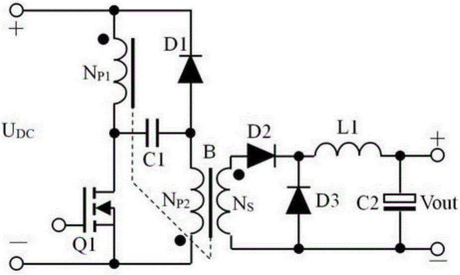
[0037] figure 1 It shows the schematic diagram of the forward switching power supply of the first embodiment of the present invention, including a transformer B, an N-channel field effect transistor Q1, a second capacitor C2, a first diode D1, a second diode D2, The third diode D3, the first inductor L1, the transformer B includes the first primary winding N P1 , the second primary winding N P2 and the secondary winding N S , secondary winding N S The terminal with the same name is connected to the anode of the second diode D2, and the cathode of the second diode D2 is connected to the cathode of the third diode D3 and one end of the first inductor L1 at the same time, and the other end of the first inductor L1 is connected to the second capacitor C2 One end is connected and forms the output positive, which is the + end of Vout in the figure, and the secondary winding N S The opposite end is connected with the anode of the third diode D3 and the other end of the second ca...

no. 2 example

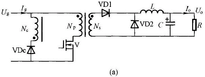
[0063] The present invention also provides an equivalent solution to the above-mentioned first embodiment, corresponding to solution 2, see figure 2 , a forward switching power supply, including a transformer B, an N-channel field effect transistor Q1, a second capacitor C2, a first diode D1, a second diode D2, a third diode D3, a first inductor L1, transformer B includes the first primary winding N P1 , the second primary winding N P2 and the secondary winding N S , secondary winding N S The terminal with the same name is connected to the anode of the second diode D2, and the cathode of the second diode D2 is connected to the cathode of the third diode D3 and one end of the first inductor L1 at the same time, and the other end of the first inductor L1 is connected to the second capacitor C2 One end is connected and forms the output positive, which is the + end of Vout in the figure, and the secondary winding N S The opposite end is connected with the anode of the third d...

no. 2 example

[0074] In the second example, the demagnetization circuit consists of D1 and the second primary winding N P2 Composition, the working principle is:

[0075] At the moment when Q1 is turned off and after that, the energy of the excitation current is not transferred to the secondary side, and the second primary winding N P2 The electric energy of the medium excitation current, its current direction is the same as that of the excitation, flows from the end with the same name to the end with the same name, flows from bottom to top, turns on D1, and this electric energy is absorbed by the DC power supply U DC Absorption, forming the excitation current demagnetization current loop;

[0076] Similarly, the first primary winding N P1 The electrical energy of the medium excitation current is coupled to the second primary winding N through no leakage inductance P2 In , the demagnetization is realized through D1, which also forms the demagnetization current loop of the excitation curr...


PUM


Abstract

The invention discloses a forward switching power supply. On the basis of a common three-winding absorption forward switching converter, the like terminal of a first primary winding NP1 in a transformer B is connected with a power supply, the like terminal of a second primary winding NP2 in a transformer B is grounded, and NP1 and NP2 are wound in a bifilar manner. A capacitor C1 is added, one end of C1 is connected with the unlike terminal of NP1, and the other end of C1 is connected with the unlike terminal of NP2, so in case of saturation conduction of Q1, both NP1 and NP2 are excited magnetically, and a secondary winding outputs energy; in case of turn-off of Q1, the energy of primary exciting current is losslessly absorbed by NP2 through D1. The forward switching power supply is suitable for working under a low voltage, and the utilization rate and the current density of the primary windings are improved, so the power density is large, large leakage inductance between primary and secondary sides is allowed, and the conversion efficiency is high.

Description

technical field [0001] The invention relates to the field of switching power supplies, in particular to a single-end forward switching power supply. Background technique [0002] At present, switching power supplies are widely used. In the industry, they are often called converters. The basic forward converter in the forward switching power supply is an ideal isolated version of the Buck converter. Common topologies include single-ended forward converters, Symmetrically drive half-bridge converters, full-bridge converters, push-pull converters, symmetrical push-pull forward converters, etc. What needs to be mentioned is the symmetrical push-pull forward converter, as shown in Figure 0-1. This figure is quoted from "Switching Power Converter Topology" written by Dr. Zhang Xingzhu, ISBN978-7-5083-9015-4 and Design, Figure 5-14 on page 91, which is referred to in this article as: Reference 1. [0003] Symmetrical push-pull forward converters are known in the patent literature...

Claims


Application Information

Patent Timeline
IPC IPC(8): H02M3/335H02M1/44
CPCH02M1/44H02M3/33523
Inventor 王保均
Owner MORNSUN GUANGZHOU SCI & TECH
Why Eureka
Try Eureka